


RS Theremin: "The day..."
Hi RS,
I can not boast any complete instruments, because I'm permanently in search, testing ideas... moreover the theremin is a minor member of my spare time eaters. I try not to make the Internet as a dustbin of partial insights and screams "eureka" (excluding various forums, of course :). Promise to think about personal webpage on worthy results.
FredM: " there is NOTHING which can be used or even seriously thought about"
My answer is your words to RS Theremin: "A few words of plain low tech english ... tells you EVERYTHING".
Sorry Fred, u are not ready. Let's consider my words as an indicator, as an litmus paper for peoples whose ideas are in resonance with my own.
New Mixer Topology
Posted: 3/2/2013 7:37:14 AM
Posted: 3/2/2013 7:54:07 AM

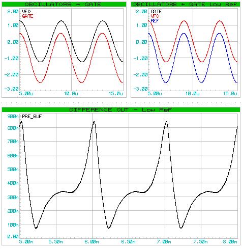
Fred, your Henk-simulation is incorrect. In reality there occurs clamping but no clipping, the variable osc's amplitude is not bigger than those ~3.7Vpp.
In my opinion, the demodulation principle is the same as in your switching circuit, it is and it remains a simple two-quadrant multiplication. The fact that your output waveform is much "cleaner" is IMHO due to the fact that you just ***tadaa*** reinvented the switched capacitor low pass filter. When pulsed, the internal MOSFETs of the 4016 behave together with the loading capacitor like a simple RC low pass whose time constant depends on the duty cycle of the switching signal: tau = C * R = C * Ron * (Ton + Toff)/Ton which explains that your signal gets the more cleaner the shorter the duty cycle because this will increase the value of the virtual resistor.
I hope for you that my perception is wrong and that you are really on the way to discover something great and new!
Posted: 3/2/2013 11:12:10 AM

From: Eastleigh, Hampshire, U.K. ................................... Fred Mundell. ................................... Electronics Engineer. (Primarily Analogue) .. CV Synths 1974-1980 .. Theremin developer 2007 to present .. soon to be Developing / Trading as WaveCrafter.com . ...................................
Joined: 12/7/2007
Reply to Thierry's: "it remains a simple two-quadrant multiplication":
"In my opinion, the demodulation principle is the same as in your switching circuit, it is and it remains a simple two-quadrant multiplication." - Thierry
Sorry Thierry, but you are completely and utterly wrong!
If one reduces the waveform on the gate so that there is no clipping, and the waveform is operating in the resistive region of the fet, then the Henk mixer is behaving like a multiplier.. As this is what is happening, the Henk is even further removed from my design than my simulation.. I pushed my simulation to extremes to test if it could be behaving like my sampling mixer.
The proof is in the eating of the pudding.. A two quadrant multiplier will presented with a square or waveform on one input, and a different (say ramp) waveform on the other input, will never produce a difference waveform which is an exact replica of the ramp... With my system I present pulses (effectively extremely short sampling pulses < 50ns in effective width) at one oscillators frequency, and ANY waveform at the other input, and the output is an EXACT replica of the waveform on the input being sampled.
My scheme IS NOT a multiplier! , you are simply WRONG!

Here is a simulation of the conditions you specify - It clearly demonstrates the difference.. With my scheme, the waveform would be exactly the same as the VFO waveform (in this case a pure sine wave) - Regardless of what the VFO waveform was!
The Henk is a lovely mixer, but has NO SIMILARITY to my mixer!!
I am really surprised that you cannot recognise this!
Posted: 3/2/2013 12:14:28 PM
Fred, you remember me the Dr. House: "It's NOT lupus!"
But it's lupus though! If you tell that I am completely and utterly wrong, you'll have to prove that Mr. Fourier was completely and utterly wrong...
The Fourier coefficients of a PWM signal with the duty cycle D between 0 and Vx volts can be calculated:
An = 2 * Vx * sin(n * pi * D) / (n * pi)
We use the approximation: sin(x) = x which is only but very exact for small values of x, resulting from the very short duty cycle D. Thus we simplify in two steps:
An = 2 * Vx * n * pi * D / (n * pi) = 2 * Vx * D
which is constant as long as the voltage Vx and the duty cycle D don't vary. That means that we get A1 = A2 = A3 etc.
Multiplying this with any signal Vin means that the resulting waveform will be the closer to the original Vin's waveform the smaller your duty cycle D is because all its harmonics will be multiplied with (almost) the same coefficient.
I hope that you are not upset because I demonstrated that it is multiplication though, but that you are happy that your experimental results are now mathematically proven. :-)
"It IS lupus!"
Posted: 3/2/2013 12:53:33 PM
From: Eastleigh, Hampshire, U.K. ................................... Fred Mundell. ................................... Electronics Engineer. (Primarily Analogue) .. CV Synths 1974-1980 .. Theremin developer 2007 to present .. soon to be Developing / Trading as WaveCrafter.com . ...................................
Joined: 12/7/2007
THIS IDEA AND THE SCHEMATICS ETC RELATED TO IT ARE UNSUITABLE FOR ANYONE WHO DOES NOT UNDERSTAND SAMPLE AND HOLD CIRCUITS, AND FOR ANYONE NOT ABOVE BASIC ELECTRONIC HOBBYIST LEVEL.. YOU CANNOT EXPECT TO JUST BUILD THESE CIRCUITS AND HAVE THEM WORK WITHOUT UNDERSTANDING THEM AND DOING THE REQUIRED ADAPTATIONS TO FIT THE APPLICATION! << This warning was added on 3/29/2013 1:18:28 AM >>
"Multiplying this with any signal Vin means that the resulting waveform will be the closer to the original Vin's waveform the smaller your duty cycle D is because all its harmonics will be multiplied with (almost) the same coefficient." - Thierry
Aw, Cmon! - That is just being bloody pedantic to the extreme!..
What you are in effect saying (and technically / mathematically you are probably "correct") is that all sampling instruments - all the keyboards and sampling synths and everything like that - Are not sampling instruments at all - they all operate on heterodyning! They all employ multiplication! they are all using the Henk mixer or some equivalent thereof!
LOL ;-) .. This is utter nonsense ! I have you and that Russian effectively shouting "Nah, nothing new here - Weve all done that! Everyones done that! What you getting so excited about !? "
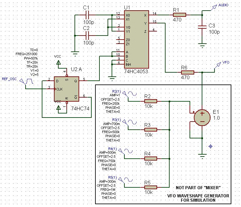
Here is my full circuit:
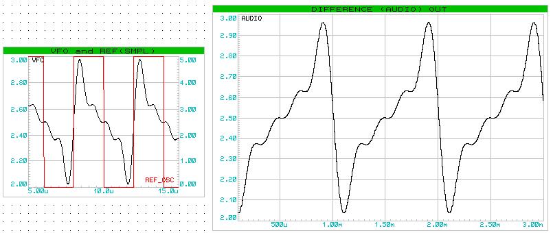
Showing replication of VFO waveform shifted to audio:
And here is a more complex waveform perfectly replicated: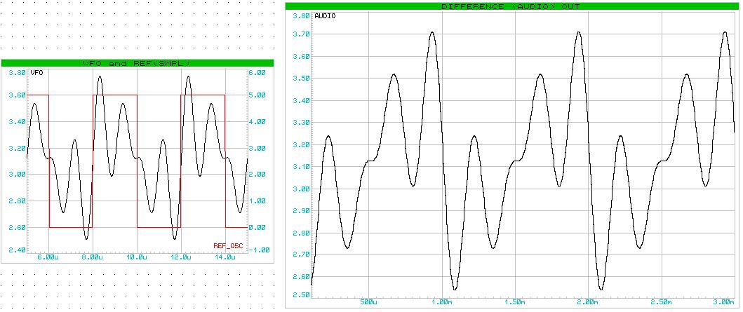
(Note - the horizontal axis is "flipped" but this is due to phase inversion, if the REF was lower frerquency than the VFO, it would look the same - the harmonic content of the waveforms are identical)
Worth noting are the values of R1 and C3 - This is NOT an audio filter or low frequency integrator to get rid of "difference" components - the roll-off (-3db) is at about 3.5MHZ ! - it could be set to 10MHZ or even higher with no problem..
But there is no need to do that - I just did this to demonstrate that the function of this capacitor is not a filter! One could drop the "rolloff" frequency right down to 250kHz without there being any impact on the waveform (other than integration / smoothing the steps)
It is not being used as a filter! This is a SAMPLE holding configuration which operates in conjunction with C1 and C2 (one of which is connected alternately across C1 while the other tracks the VFO signal).. This configuration allows the tracking capacitor to obtain an accurate sample, and the function of an extremely fast sample pulse to be obtained without the usual problems related to using a short sampling pulse.
There is no audio filtering, none is required (as you can see from the waveform) - there is NO "Switched capacitor filter" **Taa Daa** function being implemented in any way - Hell, I work with switched capacitor filters regularly - use them with VC PWM to implement voltage controlled filters sometimes.. I can recognise one when I see one! ;-)
If one was MIXING (multiplying) a short pulse with the VFO signal, one would end up with a low level difference signal and loads of HF one would need to clean up with an audio filter (like what I have in the "Henk" simulation or better) which would have a roll-off frequency at say 5kHz... One would, with multiplying, have an output consisting of SUM and DIFFERENCE signals - but with my system you get NO SUM COMPONENTS! You get only a difference frequency sampled waveform stepped at the sampling frequency.
Below is shown an expanded section of the difference (audio) waveform - this is the raw waveform from the circuit - no audio filtering or processing appled - one can see the clean sample steps which occur at the fixed Reference oscillator frequency:
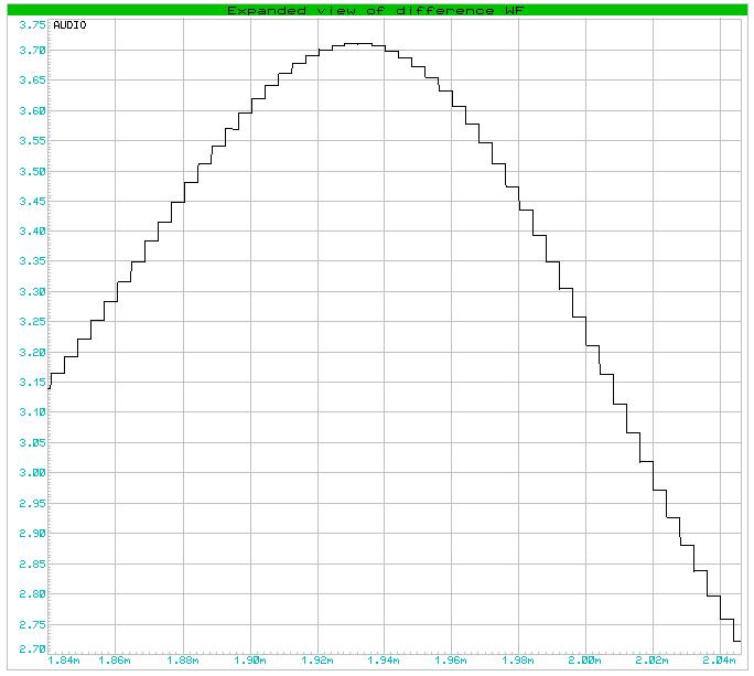
In terms of audio quality, the sampling rate is the reference oscillator rate - say 250 ksps. 96 ksps is high quality - 44.1ksps is CD quality! The dynamic range is analogue - not quantised to any number of bits... The whole system is analogue.
I defy ANYONE to show me ANYWHERE that someone else has done ANYTHING like this for the theremin!
I also defy ANYONE to show me ANY other analogue theremin circuit which has such versatility in terms of wave shaping - A circuit where one can simply change one of the input waveforms and get that waveform replicated exactly as audio...
Or, for that matter, any analogue waveshaping which is not subject to variation as a concequence of frequency as post-mixer processing is.. for example, a couple of diodes capacitor used to distort the wave-shape from the VFO will create a waveform which will appear at audio frequencies across the entire audio spectrum, without change - Try doing that with some diodes and a capacitor tacked post-mixing!
As I said earlier, I dont actually care what "type" of "mixer" or "sampler" this is - All I really care about is that it behaves so excellently and does what I want and what could be extremely useful to future theremin developers.
Added: What follows is me trying to understand how Thierry insists that this scheme is a multiplier - I am bending over backwards to accommodate this idea against what I am seeing.. But I now no longer believe there is any rational basis for declaring my scheme "just a mixer" and that he has his head so far into his mathematical box that he no longer sees daylight.
Ps.. It may be a "multiplier" - But if one is multiplying any variable by 1, or a value so close to 1 that the result is so close to the value of the variable that the error is not discernable, is there any point in calling it a "multiplier" ?
This is effectively how my scheme works ! .. The width of the sampling pulse is so tiny compared to the width required to influence the function, that it can be disregarded.
Therefore there is NO effective multiplication (other than by unity, which can/should be disregarded) occurring at the frequencies I am sampling! - If we assume a 50ns sampling edge (and with the circuit I show it is only the edge where the sample is transferred to the output - it is effectively a way to generate the function of an extremely short sampling pulse without having the problems of tracking and charge transfer) then the influence of the width will only kick in significantly (as in, a multiplier type function become relevant) at frequencies of probably about 10MHz - For an absurdly high frequency theremin with its oscillators running at 1MHZ this would mean that probably the 10th harmonic would start to suffer detectable attenuation..
For a theremin with oscillators running at ~250kHz, we are talking about detectable harmonic attenuation starting way above the 30th harmonic..
So sure - If one wants to replicate audio waveforms with harmonics way above human hearing, "multiplier" aspects may become noticable!
So, for all PRACTICAL purposes, I restate : THIS SCHEME IS NOT A MULTIPLIER! - YOU ARE WRONG!
Posted: 3/2/2013 1:49:51 PM
It has perhaps not yet been used on theremins, there you are most probably right. But there is more under the electronic sun than only theremins and this kind of switching/sampling/filtering has been used in telecom equipment since the late sixties.
Finally I feel that you have not yet fully seen the potential behind this kind of circuit... Because it allows not only to mix the original waveform down in a way that the harmonic content remains unchanged by using very short duty cycles, but you will even be able to amplify selectively certain harmonics and reducing others, only by carefully selecting a precise duty cycle which in such an application would be not as small.
edit: closing your eyes will prevent you from seeing the wolves, but the danger will remain in place. And please stop shouting. It's ignoble.
Posted: 3/2/2013 2:03:34 PM
From: Eastleigh, Hampshire, U.K. ................................... Fred Mundell. ................................... Electronics Engineer. (Primarily Analogue) .. CV Synths 1974-1980 .. Theremin developer 2007 to present .. soon to be Developing / Trading as WaveCrafter.com . ...................................
Joined: 12/7/2007
"Finally I feel that you have not yet fully seen the potential behind this kind of circuit... Because it allows not only to mix the original waveform down in a way that the harmonic content remains unchanged by using very short duty cycles, but you will even be able to amplify selectively certain harmonics and reducing others, only by carefully selecting a precise duty cycle which in such an application would be not as small." - Thierry
Oh, I have seen that potential - Originally I was playing with this idea with that object as my primary focus - as you may deduce from my original posting... In this mode, one is dealing with multiplication.
I admit though, that the mathematical complexity involved to achieve specific harmonic "creations" using PW in combination with other waveforms is outside of my comfort zone - And here is where our huge difference lies I think.. You can visualize in mathematics, I cant.. I can visualise in terms of circuit operations and wave shapes..
So, for me, the ability to manipulate a single waveform rather than having to manipulate two waveforms and deduce the result, is a great boon..
You may well get more fruitful results from multiplication!
Fred.
"And please stop shouting. It's ignoble."
I think I have reason to shout .. ignoble or not! - I do get P*ssed off by being subjected to continuos negetive nonsense like "its not new, Henk did it" " "GHZ DSO's Do that" "Its been done in comms since the 60's"..
Apart from Dewster, there has not been ONE positive comment!
Yeah! I have good reason to shout in frustration and dissapointment at how this "community" (particularly the "technocrats") behaves.
And once again I ask myself why the f**k I waste my time throwing pearls to the swine.
I actually feel I understand Anthony Henk and empathise with him - I may well do what he did.
Fred.
Posted: 3/2/2013 2:50:11 PM
From: Eastleigh, Hampshire, U.K. ................................... Fred Mundell. ................................... Electronics Engineer. (Primarily Analogue) .. CV Synths 1974-1980 .. Theremin developer 2007 to present .. soon to be Developing / Trading as WaveCrafter.com . ...................................
Joined: 12/7/2007
"My answer is your words to RS Theremin: "A few words of plain low tech english .. tells you EVERYTHING". Sorry Fred, u are not ready. Let's consider my words as an indicator, as an litmus paper for peoples whose ideas are in resonance with my own." - Ilya
The utter dishonesty in the above is astounding! Taking the bits from what I said: "A few words of plain low tech english and a schematic tells you EVERYTHING" - But remove the vital words to entirely twist what I said!
"Sorry Fred, u are not ready." -
Too right im not!!
Fred.
"My answer is your words to RS Theremin: "A few words of plain low tech english .. VITAL WORDS >> "and a schematic" << REMOVED. tells you EVERYTHING". Sorry Fred, u are not ready. Let's consider my words as an indicator, as an litmus paper for peoples whose ideas are in resonance with my own." - Ilya
Posted: 3/2/2013 3:50:10 PM
Fred wrote: And once again I ask myself why the f**k I waste my time throwing pearls to the swine.
I cannot talk for Ilya since I do not know him, but only for myself.
I must admit that I was simply deceived. I saw the thread's title "New Mixer Topology" and expected something revolutionary and new - a "pearl" citing your words. But I felt soon intuitively that the circuit which you showed and the principle which you exposed were only a very special or particular but interesting case of common two quadrant multiplying. I made the effort though to not only rely on my intuition but I provided the complete mathematical proof so that everybody could retrace it.
And for that, you treat people like me as "swine"? Thanks a lot! You are perhaps right, "swines" like me do most probably not "deserve" your "pearls".
Posted: 3/2/2013 4:00:03 PM
From: Eastleigh, Hampshire, U.K. ................................... Fred Mundell. ................................... Electronics Engineer. (Primarily Analogue) .. CV Synths 1974-1980 .. Theremin developer 2007 to present .. soon to be Developing / Trading as WaveCrafter.com . ...................................
Joined: 12/7/2007
"I must admit that I was simply deceived. I saw the thread's title "New Mixer Topology" and expected something revolutionary and new" - Thierry
And that is what you got.
The fact that you dont see it, or dont want to admit it - and that you pretend it is just a multiplying mixer when any idiot can see that its not - and you are certainly no idiot! .. Well, that is is your issue, not mine.
This is Theremin World - I present a new THEREMIN circuit and get lambasted because something similar MIGHT have been used in something else "under the electronic sun".
I do not think you (or anyone else here) are swine - But I do think sometimes people behave like swine.. And this thread has been an example IMO of such behaviour.
" I provided the complete mathematical proof so that everybody could retrace it."
The proof is, in the context of the frequencies and sample pulse width I am using, completely redundant. As I explained, it only becomes a multiplier (in practical terms) when the multiplicand deviates from unity by a noticable (measurable) quantity - The way I am operating this scheme, multiplication, in every practical way, does not occur.. Every coefficient of importance (as in, relevant to hearable harmonics for the frequencies I am dealing with) effectively multiplies with a value so close to unity that the multiplication is irrelevant.
But you know this. Even with my hugely inferior mathematical ability I can see this in your "proof", so there is no question that you can see it..
In real practical terms you are wrong, even if at the level of pure mathematical perfectionism you are right.
In PRACTICAL terms, there is absolutely NO similarity between the Henk multiplying mixer (or any other multiplying mixer where two waveforms are multiplied together, whether two or four quadrant) and my synchronous sampling scheme.
Fred.
You must be logged in to post a reply. Please log in or register for a new account.