Let's Design and Build a (simple) Analog Theremin!

Posted: 4/10/2023 7:50:13 PM
Buggins

From: Porto, Portugal

Joined: 3/16/2017

Mixer and voltage controller amplifier. OTA approach.

After playing with OTA (operational transconductance amplifier) as theremin output buffer with current sensing (see this post in wallin oscillator thread),
I've designed not very simple, but high quality analog mixer (multiplier) for analog theremin.

LTSpice model: github link


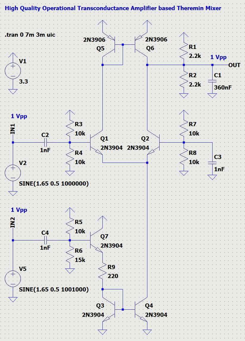
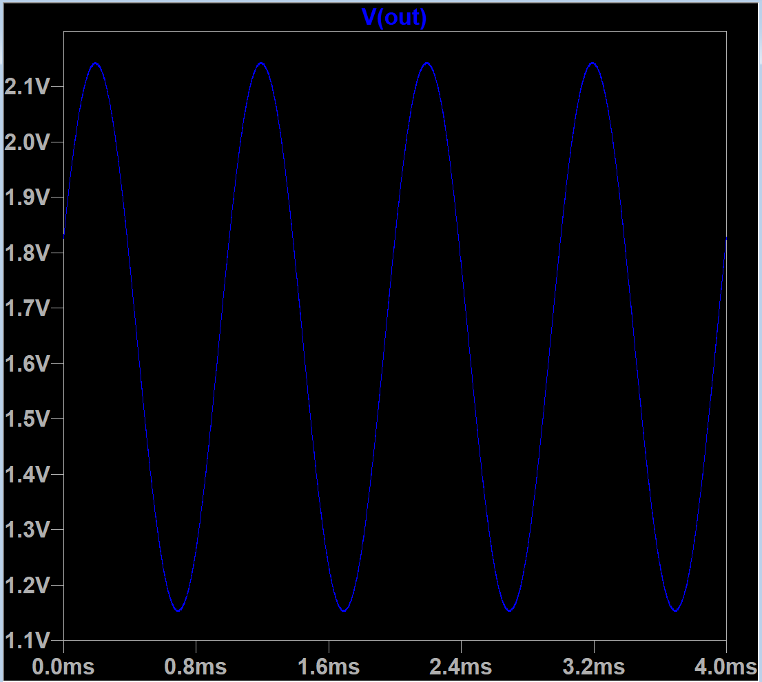
For two pure sine 1 Vpp input signals near 1MHz with 1KHz difference, output signal 1 Vpp has low harmonics level for both low frequency (2,3,4 KHz) and high frequency (1,2,3... MHz) are about 57dB.
Differential amplifier with current output on Q1..Q6 which amplifies input signal IN1 is controlled by voltage to current converter on Q7, R9 - by voltage from input IN2.
Output current is being filtered (integrated) by C1 to get rid of RF frequencies in output.

This mixer is powered from 3.3V
To work from different voltages, some tuning may be required (R9, C1).
Input voltage ranges may be changed from 1 Vpp (up to 1.5Vpp for IN1 and 2.5Vpp for IN2) or lower values, but may require changing of bias points using R3-R8.
Output voltage range is tuned to be 1V p-p, centered at VCC/2 (1.65V), but it can be changed by R1, R2, C1.
Supports input frequencies in a wide range: works fine with 10Mhz and 100KHz (but on lower frequencies, RF LP filter passes more high frequency to output.)

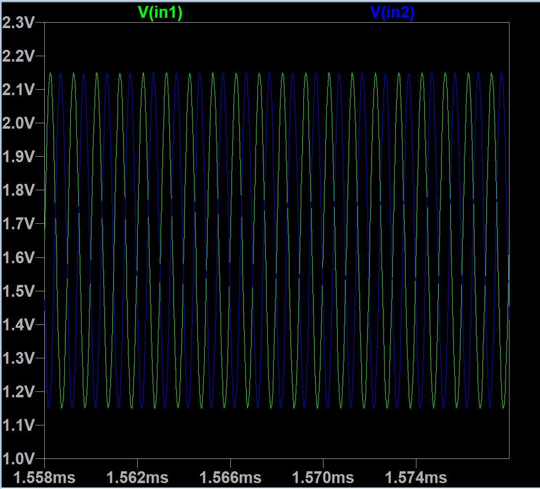
Inputs: 1Vpp 1Mhz and 1.001MHz

Output: 1001KHz - 1000KHz = 1KHz


Of course, pure sine output is not the best waveform for theremin, but it may be turned into non-sine by changing of one of or both inputs from sine to some more interesting sounding wave.
As well, some distortion / shaping stage may be added after mixer input.

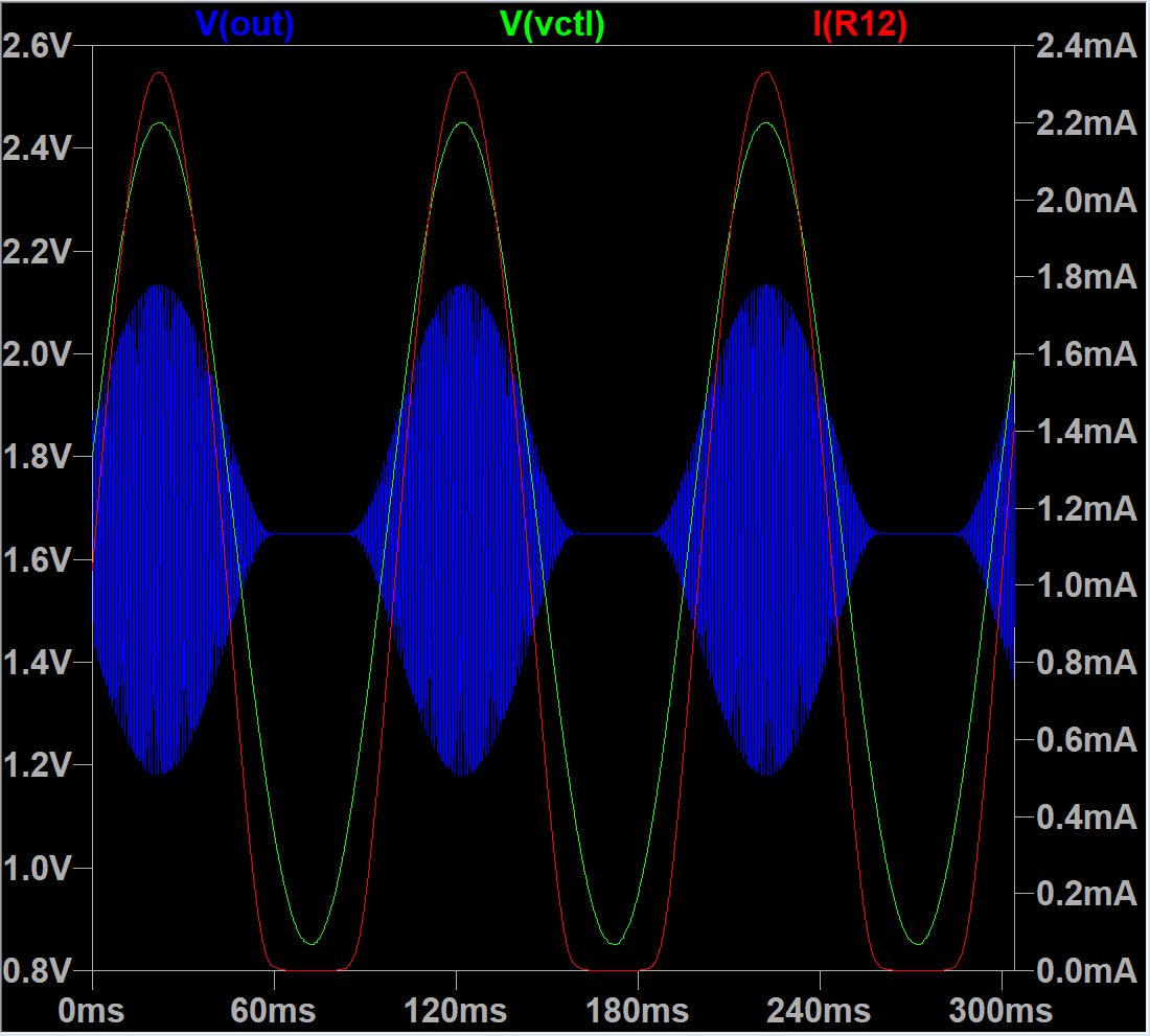
Similar approach with additional OTA stage can be used to add VCA for volume control.
Moreover, this schematic may be used as is to work as VCA - with output of mixer fed to IN1, and volume control voltage - on IN2 input.

Let's try...

LTSpice model: github link


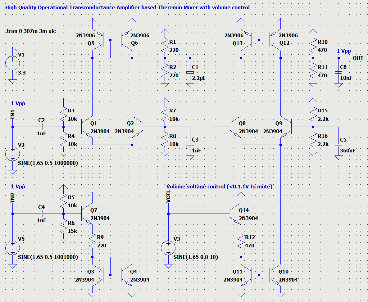
Volume control is logscale below 1.4V and almost linear for higher voltages. By choosing of voltage control working input range, it's possible to change linearity.

This schematic can be tuned for different waveforms - between pure sine and almost square by changing of diff cascade overload.

I think, waveform shaping can be made adjustable - by placing pot somewhere.


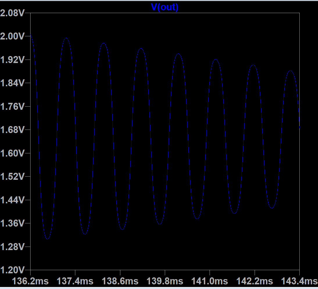
Second stage amplifier filters out RF even more, giving clean signal.


This schematic is big enough (14 BJTs). But transistors are cheap now, so it should be inexpensive.
As well, we can try to use OTA ICs (e.g. LM13700 NE5517 OPA615 OPA860 OPA861), but all of them cannot be driven by 3.3V instead of discrete BJTs, and they are more expensive.

TBD:
- design "mixer" to generate volume control voltage from volume fixed and variable oscillator signals. Can it be done on OTA?
- design good OTA based current sensing oscillator for theremin (VFO)
- design good and stable "fixed" frequency oscillator which can be slightly adjusted with a pot (can it be done w/o varistors?)
- design some waveform shaper with pots control to make sound more interesting
- combine all listed above togeher to make an analog theremin

P.S: Is pitch antenna linearity a real problem?


Posted: 4/14/2023 12:58:10 PM
JPascal

From: Berlin Germany

Joined: 4/27/2016

Thank you, Buggins, for sharing the schematics and simulation files! Hard to believe how clean the sine wave voltage is after the mixer. For me, the volume control is also a very good suggestion to rebuild and vary.

Posted: 4/15/2023 11:29:53 AM
dewster

From: Northern NJ, USA

Joined: 2/17/2012

"I've designed not very simple, but high quality analog mixer (multiplier) for analog theremin."  - Buggins

I think a bits and pieces approach like this is generally the way to go.  Surface mount transistors and passives don't cost much and will likely never disappear, and the build can be easily automated so complexity isn't a real issue.

"P.S: Is pitch antenna linearity a real problem?"

I would say yes.  Hand C really dominates in the near field, swamping body C, so you have much finer control there.  But if the near field is non-linear it tragically tends to get avoided.  Accidentally touching the non-insulated antenna and having it squeal like a pig is another danger to be found in the analog near field.

Posted: 4/15/2023 11:41:45 PM
Buggins

From: Porto, Portugal

Joined: 3/16/2017


Hard to believe how clean the sine wave voltage is after the mixer. For me, the volume control is also a very good suggestion to rebuild and vary.

It might be a problem actually. Pure sine sounds bad.
I've tried to produce non-sine signal from this mixer by distorting of one of inputs - but it still gives sine wave on output.
Even if one of inputs is square - there is still sine on output.
It looks like both mixer inputs should be non-sine to have non-sine output.

Fortunately, OTA has "overdrive" mode which uses wider, non-ninear range of atan() shaped transfer characteristic.
Varying of working range of OTA allows to sweep between pure sine and almost square.
Interesting how does this squarish waveform sound like... I'm going to export waveform from LTSpice to WAV file to check...

I think a bits and pieces approach like this is generally the way to go.  Surface mount transistors and passives don't cost much and will likely never disappear, and the build can be easily automated so complexity isn't a real issue.

Makes sense. 6-BJT OTA looks like nice building block. Below, see 12-BJT current sensing oscillator model.
Main part of analog theremin 4 oscillators + 2 mixers would already require 74 transistors (12 OTAs)...

I would say yes.  Hand C really dominates in the near field, swamping body C, so you have much finer control there.  But if the near field is non-linear it tragically tends to get avoided.  Accidentally touching the non-insulated antenna and having it squeal like a pig is another danger to be found in the analog near field.

Etherwave gives almost the same pitch when hand is very close to the antenna and if I touch the antenna.
Is it due to its linearization coils trick?
Are other analog theremins, w/o linearization coils, unplayable in near hand range?


Played a lot with LTSpice simulations of transconductance amplifiers.
Finally I've figured out how to make good current sensing oscillator on OTAs.
Extremely low phase error is achievable - 1 ns delay between LC tank current and drive signal voltage.

Two transconductance amplifier needed - one working as voltage follower and one as current sensing and drive signal shaping.
First OTA based voltage follower is loaded on LC tank.
Second OTA should have bigger gain - for compression of output range. It's loaded on resistive load.
Achieved bigger gain using extending of input voltage with additional resistor on voltage follower output.
Tried alternative - reducing of voltage follower gain with resistors on emitters in diff cascade, but it seems to be worse.

LTSpice model to play with is available on github.

Component values selected for minimizing of phase error and maximizing antenna voltage swing.
Draws 35 mA from power supply.
It's possible to tune for more sine like signal and less power consumption, in price of less voltage swing and probably bigger phase error.


On inductor with 120 Ohm serial resistance, from 3.3V power supply, it gives 4mA 1.45Vpp drive signal with nice symmetric almost sine waveform producing 160Vpp on antenna.

LC tank current and drive voltage:


Voltage swing on antenna:

The same schematic can be used as a current sensing analog front end for digital theremin.

In this case, SENSE output should be disconnected from positive inputs of OTAs, external drive input signal will be used instead.
Output buffers should be added for REF (first OTA output) and SENSE (second OTA output) for analog front end.
I'm expecing that when drive and LC tank current are in phase, difference between two outputs is close to zero (less than one nanosecond).
It can be used even in D-Lev next-gen analog front end.
Square drive output of FPGA may be converted to sine with acceptable voltage swing using some simple RLC filter.
Zero phase shift for resonant frequency is not a problem for FPGA PLL.


UPD:

How to deal with hand positions close to antenna and hand touching antenna?
1) add serial capacitance between drive and LC tank. If hand is modelled as shorted to ground, effectively this serial capacitance becomes the only C in LC.
Serial 220pF cap reduces (C_ant+C_hand) sensitivity by 4%. 100pF - by 9%, 47pF - by 17% (actually, frequency change range reduces by sqrt() of C sensitivity).
When hand touching antenna is modelled by C_hand and R_body connected serially, it's harder to keep the cirquit oscillating for R_body 10K..330K.
2) increase R3 to 100-200 Ohm to increase second OTA gain. Additionally, one more resistor can be added before R3 - once side to Q2,Q4 collectors OTA current output, another side to Q2 base and R3.
I'm not sure what is a proper model for hand touch and hand very close to antenna, but I believe it's possible to tune double OTA for suitable behavior in these cases.
Good behavior for oscillator while hand is touching or close to antenna: keep oscillation, without big frequency drop.
Can such workaround work as linearizing cirquit? Like linearizing serial C instead of serial inductors?

Posted: 8/17/2023 10:01:39 AM
Buggins

From: Porto, Portugal

Joined: 3/16/2017

Several current sensing oscillator LTSpice models are available here on github

Recent one: built using 15 BJTs.
Automatic gain control allows to keep oscillation when hand touches antenna.

Uses fast voltage follower (0.5ns propagation delay).
Power supply: 4.5V 45mA
Inductor: L=2mH R_serial=20 Ohm
Phase error: 12ns
Drive: 2.2Vpp 24mA smooth square
Antenna voltage swing: 800 Vpp
May be tuned to be closer to sine (20-40dB harmonic) but with smaller antenna swing.


You must be logged in to post a reply. Please log in or register for a new account.