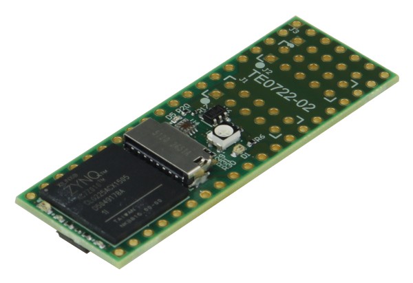
Trying to figure out if CMod A7-35T is suitable for digital theremin.
CMod A7-35T is small 48-pin DIP board based on Artix 7 FPGA with 20K LUT6, 40K FFs, 225KB block RAM, 90 DSP slices.
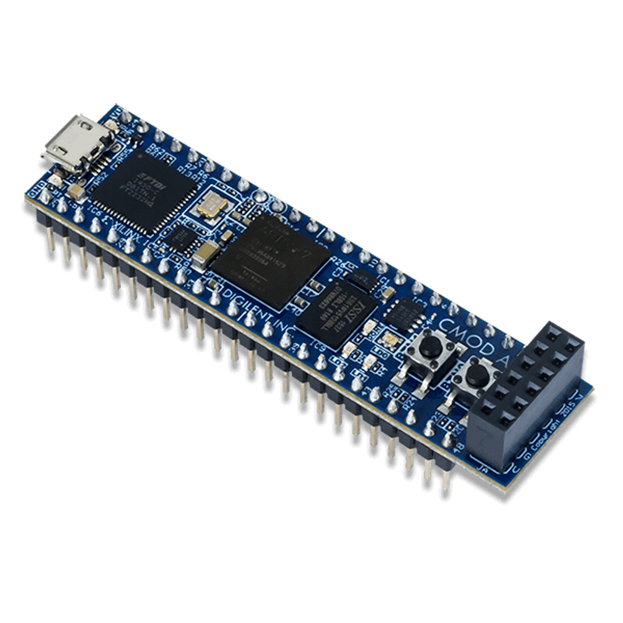
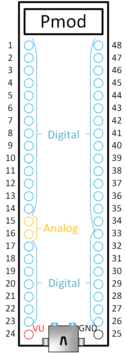
Provides 44 digital I/O pins, and 2 ADC inputs via 48pin headers, and 8 I/O pins via PMOD connector.
In stock on mouser and digikey for $100.
Has on-board 512KB SRAM chip with 8-bit interface and 125MHz max clock.
On board 4MB QSPI flash - for configuration. Part of it can be used as user storage (bitstream takes about 18Mbits, leaving ~14MBits free).
Probably, it would be possible to update configuration bitstream in QSPI flash from PC using FPGA (softcore CPU) - in this case no JTAG programming tools will be needed for updating of bitstream.
MicroUSB connector for power, JTAG, and serial. Can be programmed via USB. Configuration / presets may be uploaded to board using usb-serial.
Of course, unfortunately, this board has switching power supply (LTC3569).
Let's try to figure out if CMod A7 has enough pins to implement theremin of dream.
The heart of theremin is a sensor. Two sensors.
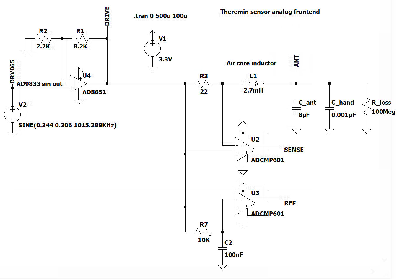
Cool sensitive and noise immune sensor I'm planning to use will be a PLL front end with current sensing, direct digital synthesis based pure sine wave drive signal (AD9833), opamp buffer/amplifier for drive signal, two comparators with LVDS outputs - one for reading of drive signal (REF), and second for current sensing (SENSE).
REF and SENSE lvds outputs will occupy 4 pins of FPGA per sensor. LVDS input on 3.3V bank of Xilinx Series 7 FPGA is working only with external terminating resistor.
AD9833 needs one 25MHz clock for ACD/DDS, and 3 signals for SPI control interface (CLK, CS, MOSI) to update DDS frequency.
Let's provide differential clock signal to sensor AFE to minimize noise.
The same clock may be reused for both DDS and SPI control interface. Xilinx Series 7 3.3V I/O bank cannot provide LVDS output, but we can just output complementary signal on two CMOS33 pins and then receive it in sensor using comparator.
So, 2 pins shared between both sensors will be used as differential clock.
As well, we will need 2 output pins for SPI - CS and MOSI (SPI CLK is shared with DDS clock).
Total number pins required for two sensor AFEs is (2+2+2)*2+2 = 14
Probably this approach is an overkill, and too expensive, but I really want to try it.
Audio interfaces are also important.
For high quality I/O we can put S/PDIF input and output modules - 2 pins.
As well it's useful to have analog audio connectors - Line Out, Line In, Mic In, Phones.
For analog part let's use SGTL-5000 audio codec IC.
It will need 5 pins for I2S interface (MCLK, LRCK, BCLK, DIN, DOUT) and either 2 pins for I2S (SCK, SDA) or 3 pins SPI (CLK, CS, MOSI) - mostly to control phones volume.
Connecting SGTL5000 using SPI control would take 5+3=8 pins.
Cool theremin needs touch screen.
4.3 inch 800x480 capacitive touch LCD module from Waveshare looks like a good choice.


4 pins will be used as LCD clock and sync (HS,VS,DE,PCK).
16M colors RGB888 needs 24 pins just for color information. Less colors would be ok for us.
12bit 4K colors (RGB444) should be enough.
Capacitive touch uses SPI interface (CLK, CS, MOSI, MISO) and two additional signals (RESET, IRQ).
Not sure if RESET is really required. Probably, it can be just pulled up or down.
Probably, we can leave w/o IRQ pin (polling via SPI may be enough?).
So far, let's count pins including IRQ and RESET.
4K colors touch LCD will occupy 12+4+4+2 = 22 pins.
But some SPI pins (CLK, MOSI) may be shared between audio (SGTL5000) and touch controller.
In this case, RGB touch LCD will consume 20 pins.
So far, sensors + audio + LCD occupied 14+8+20 = 42 of 44 digital I/O pins available on DIP headers.
How can we spend 2 more digital pins?
We don't have hardware controls like buttons and encoders so far.
2 pins seems like a bottleneck. But we still can add a lot of rotary encoders and buttons.
Let's use serial connection with encoders and buttons board.
Shift registers with parallel inputs and serial output may help us.
8-bit shift register gives ability to read 8 inputs. Several registers may be connected in chain to increase number of inputs.
One encoder with pushbutton has 3 outputs to read. 6 such encoders need 6*3=18 inputs - three 8-bit shift registers will be used (the rest 6 or 7 inputs give the ability to add 6 or 7 buttons or 2 additional encoders).
LOAD signal will latch input state into all registers.
SHIFT signal will shift out latched pins state bit-by-bit
OUT signal will be used to read serial data
Of course, for reading of 24 inputs via 3 wires we will need 24 SHIFT signal pulses and one LOAD cycle.
So, 3 pins for reading of huge amount of buttons and encoders is enough.
But we have only 2 pins left unused on DIP header.
Let's just reuse some existing signal as CLK for encoders interface. E.g. it may be CLK from SPI or some clock from audio I2S interface (e.g. 48KHz LRCK gives 48000/24=2000 times per second scan rate of encoders synchronous to audio sample rate simplifies filtering out of noise from this shift register chain).
There are still two unused pins on DIP header - dual ADC pins.
We can use analog ADC pin for pit (e.g. phones volume control).
We can use analog ADC pin to read state of expression pedal (with pot inside).
Two reasonable options:
- Two pots (e.g. phones volume + reverb/effect)
- Phones volume pot + pedal
- Two pedals
It looks like DIP header of CMod A7 board provides enough pins for our cool theremin.
What about resources?
For LCD it's nice to have enough memory for framebuffer.
Onboard 512K SRAM can fit 800x480x8bit framebuffer.
To provide 12bit RGB444 from 8bit pixel we can use palette.
Or we can limit number of colors even more, to 8bit RGB (3-3-2) - it would free 4 more pins.
If we didn't need framebuffer, 512K might be used as data or code RAM for soft core - to fit bigger program.
Or, we could use it as a buffer for reverb (~5 seconds).
Unfortunately, we don't have enough free pins to connect external big RAM - for framebuffer and reverb buffer.
But there is a PMOD connecter, soldered with a bit strange orientation. It has 8 digital I/O pins inside.
Can we connect RAM to it?
We can connect PSRAM chip with QSPI interface using 6 pins of PMOD header.
Cheap 8MB PSRAM in 8-pin package are available.
Even with 100 or 133MHz clock and using QSPI mode (4-bit transfer per clock cycle and 50 megabytes per second throughput) it will be slow enough due to big latency (read and write operations take a lot of cycles).
But if batch read or write is ok (like for fetching pixel data for LCD), QSPI PSRAM seems to be useful.
Two more free pins on PMOD header.
We can use them as additional CS for SPI interface - to connect more SPI or QSPI devices.
E.g. additional QSPI Flash, and/or SD card.
Conclusion.
CMod A7-35T is good enough for usage as Digital Theremin core.
Pros:
a lot of FPGA resources (20K LUT6 is much more than 20K LUT4 of competitors, it's closer to 40K LUT5 + 40K FFs, 90 DSPs - just unbeatable)
always in-stock!!!
easy to solder connectors
now $100 price does not look too big anymore (Artix 35 chip costs about $80)
I'm familiar with Xilinx tools
Contras:
switching power supply
small size of onboard SRAM


