YAEWSBM - Yet Another Etherwave Standard Bass Mod

Posted: 3/15/2012 7:18:17 AM
Thierry

From: Colmar, France

Joined: 12/31/2007

"Goes up in smoke" was the attempt of a non-English native speaker to ask a rhetorical question... :-)

No, there are naturally no rules against publishing unripe circuit ideas on these forums as long as the author declares them as such.

There is only one point which asks (for historical reasons) for a certain "finesse": electronic engineers have come up in the last years with lots of theremin circuit designs and mods which were mostly not successful because they were designed by EEs for EEs, completely forgetting that the average theremin player is rather a musician or an artist in general. Thus the touchstone should be (after a perfect electric engineering phase) the judgment of a representative number of musicians who don't care about impedances and spectrum lines, but will tell if the circuit or the extension brings really a new and reproductible expressive quality in.

Posted: 3/15/2012 9:52:06 AM
dewster

From: Northern NJ, USA

Joined: 2/17/2012

@Me:

"This is the first I've heard of Fred Mundell or Element14..."

Oops, I stand corrected re. FredM & Element14.  I actually joined earlier this month and forgot (old brains: can't live with them, can't live without them).  It's a fascinating resource, too bad no one has posted anything there in a while.

Posted: 3/15/2012 10:21:59 AM
dewster

From: Northern NJ, USA

Joined: 2/17/2012

@Thierry:

"No, there are naturally no rules against publishing unripe circuit ideas on these forums as long as the author declares them as such."

I thought that was pretty much implied in an open public forum.  Certainly I take every lay circuit I find on the web with a huge grain of salt.  It seems like there are a million noobs out there (nothing particularly wrong with that, we all have to start somewhere) working overtime generating them like crazy.

"There is only one point which asks (for historical reasons) for a certain "finesse": electronic engineers have come up in the last years with lots of theremin circuit designs and mods which were mostly not successful because they were designed by EEs for EEs, completely forgetting that the average theremin player is rather a musician or an artist in general. Thus the touchstone should be (after a perfect electric engineering phase) the judgment of a representative number of musicians who don't care about impedances and spectrum lines, but will tell if the circuit or the extension brings really a new and reproductible expressive quality in."

The EE / musician intersection is something of a two-way street.  Over on Piano World (www.pianoworld.com) I've done lots of spectral analysis of digital pianos, exposing the horrors of butchered sample sets to musicians.  They often can't put their finger on why a certain digital piano sounds bad without some technically directed audio training.  On the other hand they have opened my eyes to many issues I wouldn't have thought of on my own.

Posted: 3/15/2012 10:56:40 AM
dewster

From: Northern NJ, USA

Joined: 2/17/2012

@Thierry:

"Fred Mundell published a very similar circuit as yours already 2 years ago on Element14."

Could you give me a pointer to that?  I've looked for about an hour and all I've found along those lines at Element14 is broken links back to thereminworld's "Possible EW Modification Board" three farily rambling threads with no apparent fruit.

Posted: 3/15/2012 11:48:05 AM
Thierry

From: Colmar, France

Joined: 12/31/2007

Schematics start with the second post in this thread 

Posted: 3/15/2012 12:21:12 PM
dewster

From: Northern NJ, USA

Joined: 2/17/2012

@Thierry:

Thanks! The title "Electronics for Theremins" was so generic I didn't think to look there.

It's not clear to me why Fred's circuit is powered only by +12 and ground (and thus needs a voltage divider for base biasing) when +/-12 and ground are available at the expansion header, which allow for simplified biasing.  Not saying it's wrong or anything.  Perhaps he was trying to prevent noise from the negative supply from ending up in the signal, but there is no real protection from this happening via the positive supply to the base.  Ah well, I'm sure there are a thousand ways to skin this cat.

Wasn't it Fred's desire to keep this an open project?

Posted: 3/15/2012 12:37:30 PM
Thierry

From: Colmar, France

Joined: 12/31/2007

It was (and I think it is still) Fred's desire to keep this an open project. Why do you ask?

In my eyes, Element14 is a very good place for exchanging among experts about such unapproved circuits because the risk is much lower there than here that someone heats his soldering iron without understanding the early and unripe development stage of this project. I'm always ready to protect the people which you call "noobs" from themselves.

Posted: 3/15/2012 3:57:31 PM
dewster

From: Northern NJ, USA

Joined: 2/17/2012

@Thierry:

"It was (and I think it is still) Fred's desire to keep this an open project. Why do you ask?"

Because I don't see the ESPE01 schematic posted anywhere?

"In my eyes, Element14 is a very good place for exchanging among experts about such unapproved circuits..."

It's kind of dead over there with no new posts in years.  I think I prefer a more open and lively development environment. 

"... because the risk is much lower there than here that someone heats his soldering iron without understanding the early and unripe development stage of this project."

Honestly, could you please stop making vaguely sinister assertions about smoking transistors and unripe development?  If you can identify concrete and specific problems with my mod I'd love to hear them.  You've spent much more time and effort than I have with this issue and by all appearances are an expert, so you of all people should be weighing in with specifics rather than scare tactics.
Posted: 3/15/2012 5:11:15 PM
RS Theremin

From: 60 mi. N of San Diego CA

Joined: 2/15/2005

A famous prophet once said: "Can we all get along", then they burnt down the city.

I thought this would be a project to try on my EWS Rev 11- 211D. Please refer to the earlier posting of the first page of this thread. Different revisions of the EtherWave Standard over the years may have different and unexpected results. Time will tell… Someone knows the revision turning point for this project to respond properly.

I need to put in a Mouser order for my other project and being this project is 90% Radio Shack would like a stock of the little caps in order to mail out all 4 if wanted along with an un-etched copper clad board cut to size at no charge. It is all about theremin advancement.

I “give away” many things theremin which encourages bulk buying.  About the EW: 15 pf capacitors C2 & C6.  Would you rather use 4, 18pf or 4, 15 pf.  These would be 5% COG. It is my feeling you had the 18 pf lying around or is this 15/18 combo an engineer thing? (-‘  It will take me a few weeks  to get to my EW. I am actually a little excited.

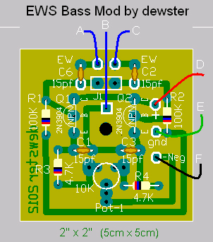
dewster said: +/-12V and ground are available at the 8 hole inline expansion point on the Etherwave, and this is where I located the prototype board.  C6 and C2 were removed from the EWS board with a solder sucker and iron, the capacitor legs were then bent outwards 45 degrees, so that they form a 90 degree angle with each other.  One leg of C6 A was then resoldered at the position where it came from, in the hole closest to the edge of the board, with the free leg of the capacitor pointing towards the prototype.  Same for C2 C (solder it into the hole closest to inline expansion point).

  B to the free hole at the C2 location (closest to the center of the board).  Because these capacitors are directly connected to the sensitive side of the LC tanks you'll want to keep these wires short and direct


PDF  116k

Posted: 3/15/2012 6:10:50 PM
dewster

From: Northern NJ, USA

Joined: 2/17/2012

@RS Theremin:

I'd say go with 15pF in place of the 18pF.

C2 & C6 belong on the main board, not on the mod board.  Otherwise you are running wires directly to the sensitive side of the LC tanks.

Why don't you align the ground, -12V, and +12V off to the right like on my vector board layout (see pins in first picture)?  That would let you run stiff pins directly down to the expansion port on the main board, physically supporting the mod board and providing power.

Otherwise the wiring looks fine.

You must be logged in to post a reply. Please log in or register for a new account.