Let's Design and Build a (mostly) Digital Theremin!

Posted: 9/21/2014 7:07:57 PM
FredM

From: Eastleigh, Hampshire, U.K. ................................... Fred Mundell. ................................... Electronics Engineer. (Primarily Analogue) .. CV Synths 1974-1980 .. Theremin developer 2007 to present .. soon to be Developing / Trading as WaveCrafter.com . ...................................

Joined: 12/7/2007

"Don't hold back, tell me what you really think. ;-)" - Dewster

I did! ;-)

I think that its the most appealing visual display I have seen - I think it would be great ant the 'flight deck' of some UFO from the movies - complete with the hieroglyphs! (Hey, dont forget - it appears I am stealing the aliens and causing problems in the aether! ;-)

I think the cost (both development and manufacture) will be well worth it from a sales potential.

As to whether it will be of any use to thereminists, I have been entirely wrong to pass any judgment or give any comment on this! - I am projecting my own disability (the fact that my visual neurons seem to impair my auditory ones) on others.. I suspect that people who have multi-core processors in their heads will fair better than me who probably has an an analogue computation engine and perhaps a small 8 bit MCU for other stuff..

;-)

Fred.

Posted: 9/21/2014 7:58:23 PM
dewster

From: Northern NJ, USA

Joined: 2/17/2012

"But now I need to check the operation of the phase-locked oscillators in practice (rather than just in theory and simulation, which seem to work). Havent done it yet - but I think the easiest way may be to connect an electronically controlled capacitor to the antennas, and drive this from a function generator."  - FredM

I'm messing with the Theremini's head to better characterize the pitch hand response time.  My Goldstar function generator grounded to the Theremini ground and with hot lead placed near the pitch antenna and set to 10Hz does nothing that I can see. 

But moving the hot lead ~1' away and setting the generator to ~280kHz really messes with it, but in a static way (moves the Theremini pitch a fixed amount for a given fixed function generator frequency). 

The Goldstar has an external FM modulation input, so I dug out my old homebrew function generator and connected it up and set the Goldstar to ~160kHz.  This gives a sine modulated pitch change from the Theremini that follows the modulation speed quite nicely.  I'm not hearing (or seeing via a recording) much Theremini modulation above ~50Hz, so the Theremini 3dB response point is likely way below this.

Here is an MP3 of a manual modulation sweep from ~10Hz to ~50Hz and back to ~10Hz:

http://www.mediafire.com/listen/4jhk8wyqmafu5k8/Theremini_10Hz-50Hz-10Hz_2014-09-21.mp3

From that I calculate -3dB to be around 15Hz.  It might actually be worse as my homebrew generator unfortunately won't go below ~10Hz (to get a good baseline response). 

Anyway, blea!

Posted: 9/21/2014 8:26:22 PM
FredM

From: Eastleigh, Hampshire, U.K. ................................... Fred Mundell. ................................... Electronics Engineer. (Primarily Analogue) .. CV Synths 1974-1980 .. Theremin developer 2007 to present .. soon to be Developing / Trading as WaveCrafter.com . ...................................

Joined: 12/7/2007

Hi Dewster,

My thinking was more along the lines of reverse biasing some diodes, and varying the reverse biasing voltage to modulate the capacitance, rather than having a signal source. But I have not tried this!

The advantage (if it works) is that one should be able to tune using DC / Offset, know the required upper and lower voltages across the diodes required for the frequency span, then modulate this voltage between these extremes with whatever waveform / frequency you want.

From a slow square wave one should be able to directly determine frequency.. In fact, you probably dont even need a signal generator, thinking about it

From a slow square wave one should be able to directly determine frequency.. In fact, you probably dont even need a signal generator, thinking about it.. Another diagram coming in a moment..... ;-)

Simply tune one capacitor (not connected to switch) for lowest pitch, the other for highest pitch when switch closed.. Some sort of actuator (string or whatever) so you dont get close as you actuate the switch (ideally this could be a H11F1 opto or  relay of some kind).

In fact, if you had small enough adjustable capacitors (or made your own from twisted wires) you could connect directly to the antenna connection point and not need to worry about any antenna related stuff..

Whatever - This is the solution to my testing! ;-)

Fred.


Posted: 9/21/2014 8:48:55 PM
dewster

From: Northern NJ, USA

Joined: 2/17/2012

Fred, I'd be very interested in whether or not either of those approaches work!  They would certainly beat something dangerously rotating around, and would give a lot more credibility to the testing results than my "interference" approach.

I suppose we all know the Theremini response time is abysmal, and I just wanted to find a somewhat reasonable number to characterize the suck without putting too much time and effort into it.

Posted: 9/21/2014 8:58:49 PM
FredM

From: Eastleigh, Hampshire, U.K. ................................... Fred Mundell. ................................... Electronics Engineer. (Primarily Analogue) .. CV Synths 1974-1980 .. Theremin developer 2007 to present .. soon to be Developing / Trading as WaveCrafter.com . ...................................

Joined: 12/7/2007

"I suppose we all know the Theremini response time is abysmal, and I just wanted to find a somewhat reasonable number to characterize the suck without putting too much time and effort into it." - Dewster

I cannot see a flaw in the simple relay / capacitor switch scheme (added above) - Hate diodes as variable capacitors.

Yes, we should be able to absolutely quantify the response time between any given capacitance's - Scientifically and with no room for uncertainty.

Wager? For the theremini I recon in the order of 100ms for the full span from ==60cm to say ==5cm, and I guess this will be the same regardless of the lowest -> highest pitches selected. (this is based purely from looking at the few swept samples you provided, and my arithmetic, so could be way out in either direction  LOL;-)

Fred.

Oh, the switch scheme will only work for determining latency - the varicap scheme or something similar would be needed to detect irregularities or pitch "stickies".

I am not sure about the varicap scheme - but I would bet my life on the switch scheme working, it really must!

One way I have made crude trimmable capacitors in the past is to use shielded audio cable, ground to screen, then cut the length back until I got to the required capacitance.

While on crazy ideas - I played with this kind of circuit a bit, but never followed it through - it seemed to work, but drifted like hell and had other issues (was horribly slow) - But it may be usable for crude testing.. I also used photovoltaic opto's to couple varicaps - this worked well, but at £6 per photovoltaic isolator, not well enough!

Posted: 9/22/2014 8:27:00 PM
dewster

From: Northern NJ, USA

Joined: 2/17/2012

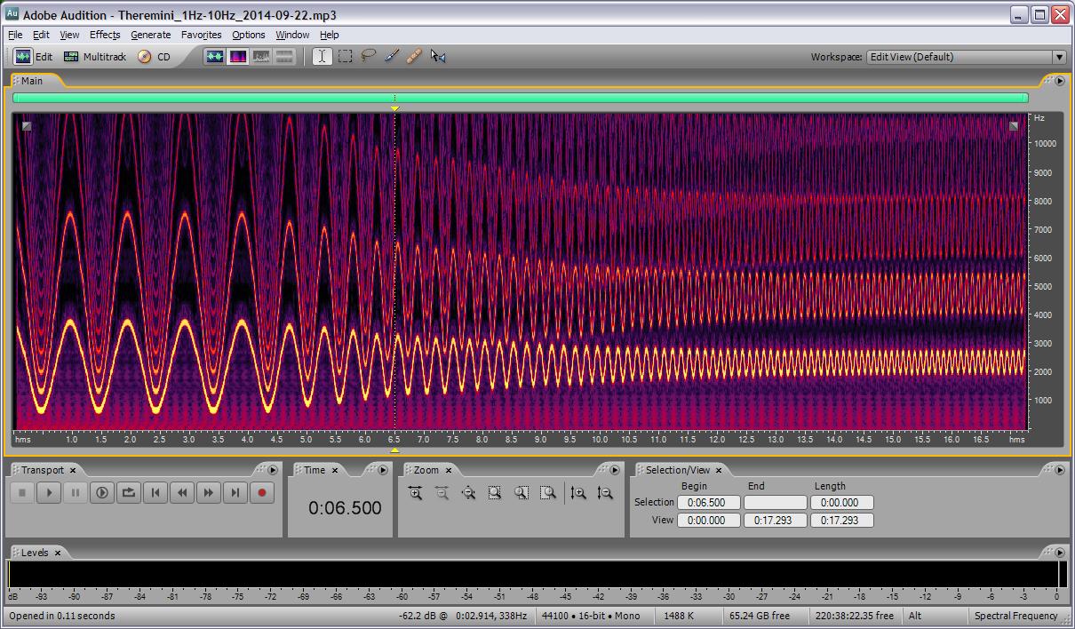
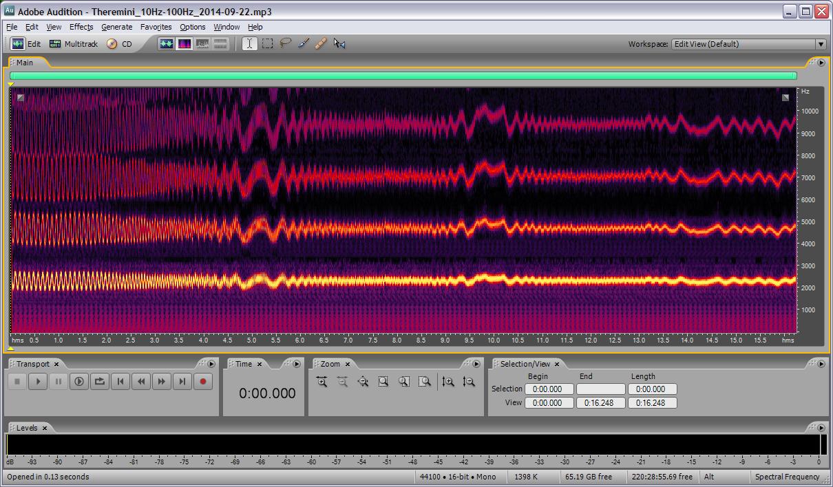
Just remembered I had an old HP function generator stashed away, so dusted it off and recreated the setup I had yesterday, using the HP as FM modulation source into the Goldstar.  This time I placed the hot lead a couple of inches from the Theremini pitch antenna and played with amplitudes and center frequency until I got a fairly nice looking FM sinusoid in the Audition Spectral Frequency view.  Recorded 1Hz-10Hz sweep, and 10Hz-100Hz sweep, files are here:

http://www.mediafire.com/listen/t75m1wpczy4mhnk/Theremini_1Hz-10Hz_2014-09-22.mp3

http://www.mediafire.com/listen/u1zdps83snf8zd1/Theremini_10Hz-100Hz_2014-09-22.mp3

Above is the 1Hz to 10Hz sweep.  I'm seeing -3dB (0.707 peak) at ~2.6Hz, which is so astoundingly bad I almost don't believe it.


Above is the 10Hz to 100Hz sweep.  Other than the expected general diminishing response with increasing modulation frequency, it appears there is aliasing of some sort going on around 33Hz, 66Hz, and 99Hz.  Hmm.

"Wager? For the theremini I recon in the order of 100ms..."  - FredM

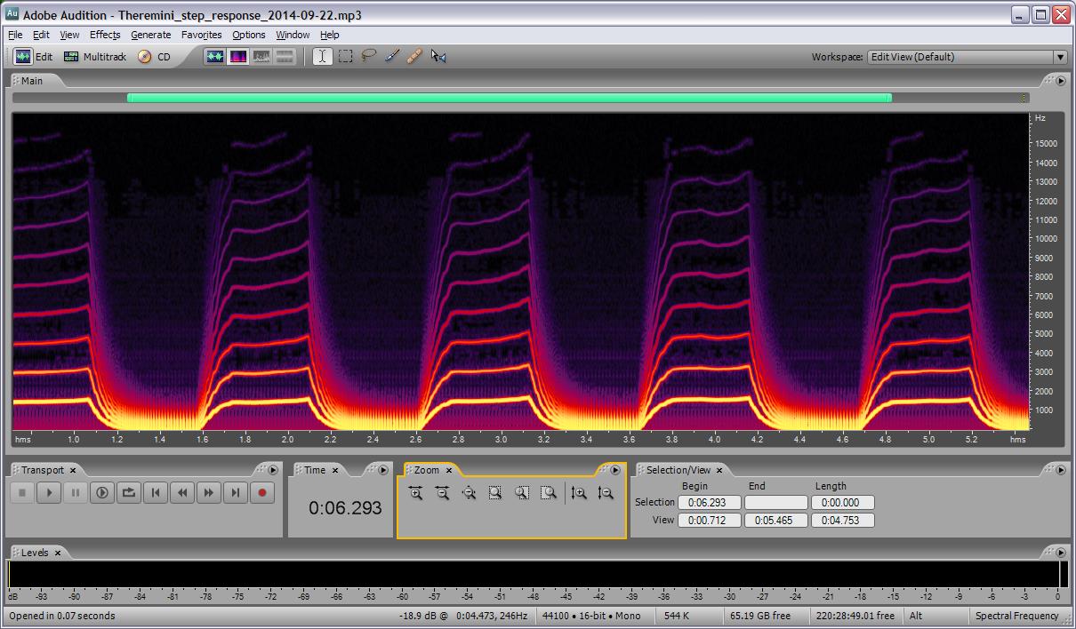
You win!  I set the modulation waveform to square with 1Hz rate and recorded the following file:

http://www.mediafire.com/listen/sf3fpo0mpdti9zp/Theremini_step_response_2014-09-22.mp3

Above is the Theremini step response.  I'm seeing 0.15sec full settling time, or around 0.1s to hit 63%.  This RC time constant corresponds to a cutoff frequency of 1/2*pi*RC = 1.6Hz.  Wow.

"I am not sure about the varicap scheme - but I would bet my life on the switch scheme working, it really must!"

I agree, though I believe rise time calculated -3dB bandwidth and directly measured -3dB bandwidth are only equivalent when the filter is a simple first order RC.  (It is likely that there are several low frequency poles in the Theremini pitch data path.)

Grain of salt with the above, I'm not totally convinced this method of testing BW is foolproof, though the step response time does seem to jibe fairly well with the frequency response, as well as your calculations Fred, so it's probably not too far off the mark.  With a response time this low I'm not surprised that even coalport finds the Theremini difficult to play.  And it stands to reason that if one can measure significantly diminished response via faster hand movements (and experience the lag directly) then the BW almost has to be below some upper limit on the order of 10Hz or so.

And with that I believe I'm pretty much over the Theremini.

Posted: 9/22/2014 10:14:30 PM
FredM

From: Eastleigh, Hampshire, U.K. ................................... Fred Mundell. ................................... Electronics Engineer. (Primarily Analogue) .. CV Synths 1974-1980 .. Theremin developer 2007 to present .. soon to be Developing / Trading as WaveCrafter.com . ...................................

Joined: 12/7/2007

"You win!  I set the modulation waveform to square with 1Hz rate and recorded the following ... " - Dewster

LOL ;-) .. My gamble was based entirely on a few measurements of your original audio sweeps - so it wasn't much of a gamble - the data was there, the only ambiguity being the extremes (as in, I could determine the 'curve' but couldn't be certain of the excitation shape or amplitude)  it couldn't have been too far from 100ms.. I was actually expecting worse than 100ms, but played cautious - dont want the M-ugh crowd to say I was exaggerating!  :-)

In musical terms it is worse, one needs near 100% - 63% is just our mathematical measurement standard - so the real time is more like 150ms.

Thanks for doing these tests so comprehensively and publishing these indisputable results Dewster!

"And with that I believe I'm pretty much over the Theremini"

I agree. This toy is so bad it cannot be converted into a usable theremin - calling it a theremin is absolute misrepresentation.

Summary of the important facts:

" 0.15sec full settling time, or around 0.1s to hit 63% This RC time constant corresponds to a cutoff frequency of 1/2*pi*RC = 1.6Hz.  Wow." - Dewster

Fred.


Posted: 9/23/2014 4:14:23 PM
dewster

From: Northern NJ, USA

Joined: 2/17/2012

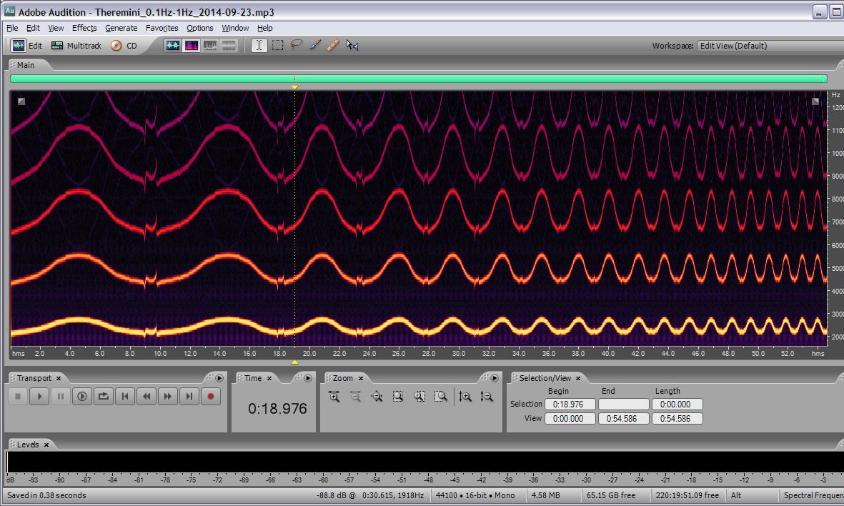
One last test of Theremini gestural pitch side BW via the FM interference method:

Above is 0.1Hz to 1Hz response with the modulation frequency in 0.1Hz steps.  This is something I should have performed earlier as a baseline.  No significant amplitude reduction over this range, which is consistent with the -3dB roll off somewhat above this range.

Posted: 9/24/2014 4:44:13 PM
dewster

From: Northern NJ, USA

Joined: 2/17/2012

DISPLAYS

I'm at the point where I need I/O (display, knobs, buttons, LEDs, etc.) and am back up against the dearth of display offerings out there.  I ordered a 20x2 line LCD from Adafruit but, having played with one of these in the past, I feel kind of nauseous at the thought of using it.  The on-board controller interface is 4 or 8 bit (no SPI option), there is no internal register you can access to adjust LCD contrast, it's 5V, etc.  The controller is also rather slow, has variable command timing, and requires initialization.  You see people all over the web adding a SPI / parallel processor onto these in an attempt to update them a bit but that strikes me as a stopgap / band-aid on a badly aging product.

Ran across this site yesterday on eBay: http://www.buydisplay.com.  Prices including postage are quite reasonable and their black on white displays look very high contrast and readable:

The control chip is what to look out for, at least one of the newer graphics ones supports SPI directly and has a contrast adjustment register (UC1701).

Not sure where this is going.  I'd like to avoid graphics as this usually means one must generate characters in SW, which would eat into the rather tiny Hive memory space (I'd rather use the space for wave tables).  One could I suppose take a hybrid approach, where graphic characters are built up of "strokes" much like a 14 or 16 segment LED display - this would compress the storage requirements but would also make for a less readable "font".

Other issues are mechanical: the newest displays tend to use flexible conductive ribbon cabling with SM connectors.  The display pictured above has thru-hole pins mounted on the glass, but they are on 0.05" centers rather than 0.1" (one could manufacture a break-out / mounting PWB, but who knows when this specialized product will be retired?).  And everything needs a bezel of some sort, I've given up on the idea of sticking the data display behind the same plexiglas as the LED tuner.

Multi-line character-only LCD (non-graphic) displays could really use a updating.

The same company above also has graphic & character based OLED offerings, and these have more modern controllers.  OLED has 16 grayscales too.  Not sure how they are generating the higher voltages OLEDs require.

Posted: 9/24/2014 10:00:35 PM
FredM

From: Eastleigh, Hampshire, U.K. ................................... Fred Mundell. ................................... Electronics Engineer. (Primarily Analogue) .. CV Synths 1974-1980 .. Theremin developer 2007 to present .. soon to be Developing / Trading as WaveCrafter.com . ...................................

Joined: 12/7/2007

Dewster,

I havent looked into this yet - but the PSoC4 seem to have a UM specifically for LCD .. At a few $, one could dedicate a little board just to interface between the FPGA and the LCD .. Tons of memory in the PSoC4, and whatever interface you chose .. Or even implement the entire UI on this board and communicate the settings to the FPGA.

Just a thought...

Fred.

You must be logged in to post a reply. Please log in or register for a new account.