


Hey dewster. While I can't be certain to understand everyhting you said in "Analog Theremins Considered Harmful" exactly, I think I catch the drift.
And am now wondering: could you, more precisely, actually mean that the thing to unlearn is the way analog theremins are typically built, using the direct difference of two RF signals as the audible waveform?
Could the things you have learned when thinking about doing things differently actually feed back into analog theremin design when attempting designs which do seperate the functional modules involved more clearly cut? E.g., distance detection, conversion to a useful curve to control the sound generator pitch, and a sound generator - maybe some sort of VCO plus some wave shaping afterwards?
I ask this just as a fan of analog sound generation and perhaps it could still be easier, if only PCB manufacturing wise, than digital stuff.
Let's Design and Build a (mostly) Digital Theremin!

"And am now wondering: could you, more precisely, actually mean that the thing to unlearn is the way analog theremins are typically built, using the direct difference of two RF signals as the audible waveform?" - tinkeringdude
Yes, measuring the frequency and offsetting it numerically is very similar to analog Theremin heterodyning. Offset heterodyning with period measurement is more complicated and can likely yield better perceived linearity, but it also gives an exponential numeric response that must be run through a log converter before being further manipulated. Measuring frequency or period directly and doing the math to give a linear number change with linear hand distance change is the direct sensor approach.
"Could the things you have learned when thinking about doing things differently actually feed back into analog theremin design when attempting designs which do seperate the functional modules involved more clearly cut? E.g., distance detection, conversion to a useful curve to control the sound generator pitch, and a sound generator - maybe some sort of VCO plus some wave shaping afterwards?I ask this just as a fan of analog sound generation and perhaps it could still be easier, if only PCB manufacturing wise, than digital stuff."
Interesting question. Squaring and inverse are involved, so doing the math via analog methods would be difficult. But then you could feed the result to analog synthesis modules (VCO, etc.) to produce the sound. Probably a lot easier to do the sensor part digitally where the math is straightforaward and then do D/A conversion going to the analog synthesizer. And easiest of all to do it all digitally. ;-)
Shield Drive C Sensor!
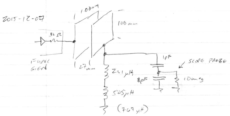
Wow, this is possibly a game-changer! Had an idea the other night to put another plate behind the plate antenna, forming a small value capacitor. This back plate is then driven with a 3.3Vp-p square wave. The front plate is tied to ground through an inductance, and the resonance at quadrature is sensed via a capacitive divider:
The front plate, being a plate, is already fairly directional to hand movement. Since the back plate is driven by a relatively low impedance, it conveniently acts like a shield, making the front plate even more directional.
I wanted the front & back plate mutual capacitance to be around 3pF, and some quick web research gave the usual formula where the capacitance is equal to epsilon 0 * the area of one plate / the distance between the plates. A roughly fist sized plate is 100mm x 100mm, and working backwards the distance between them for 3pF should be 27mm. I cut two squares of aluminum from an old NJ license plate, three pieces of 1/4" wooden dowel for spacers, and used 5 minute epoxy to glue it all together. Wood has a fairly low dielectric constant but the most stable dielectric is a vacuum (air) so we want to keep the wood to a minimum. Wood on end like this also should have a really low coefficient of thermal expansion of (~3ppm/C). So wood should be an almost ideal spacer material.
The capacitor measures around 6pF with my LC meter, which I suppose could be mutual plus intrinsic, and fringing fields could also be playing a role here. I obviously need to look into this further, as well as other geometries for the front and back plates. I stuck the capacitor in the freezer (-20C) for a while, took it out and connected it to my LC meter. I warmed the capacitor up with a hair dryer and noticed around -180ppm/C, which isn't the best, and doesn't seem directionally correct in terms of wood expansion, so I need to look into this further as well. There may be twisting of the plates going on or something.
Tossing the circuit together on my bench, and using a couple of inductors to get the resonance point down to <2MHz so I could use my function generator as stimulus, I measured about 200Vp-p on the front plate at resonance 1.71MHz, which works out to 11.3pF total as seen by the coil. In reality the back plate would be driven through a resistor larger than the 50 ohms internal to the function generator, which would lower the voltage swing somewhat. And the probe is so close to the front plate that it is likely picking up more voltage just due to proximity than through the 1pF series capacitor alone.
It's a rat's nest, but the results are quite encouraging.
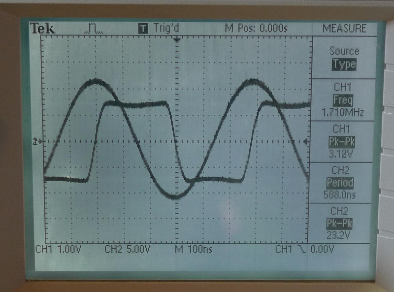
Here you can see the square drive on the rear plate (CH1) and the sine wave on the front plate (CH2) at resonance. Note the quadrature, and note also that the stimulus perhaps counter-intuitively seems to lag the response. The back plate does indeed heavily reduce the response to my hand movement in back of the antenna compared to the front. Not sure how all this affects capacitance linearity in a 1/d sense.
What's also neat about this is I will most likely be able to use a single drive plate to stimulate the three plate arrangement I'm planning on using for the left hand (3-axis controller). And directionality is desirable for band-on-small-stage type performance environments.
One could also just ground the back plate and drive the front plate via a 3pF capacitor, but this would add to the total capacitance, and therefore lower the absolute sensitivity somewhat.
Shield Drive C Sensor (continued)
I got the idea to use my separate FET sense / drive oscillator with my new shield drive plate antenna, the combo seems pretty stable. I need this to test for C vs. hand distance.
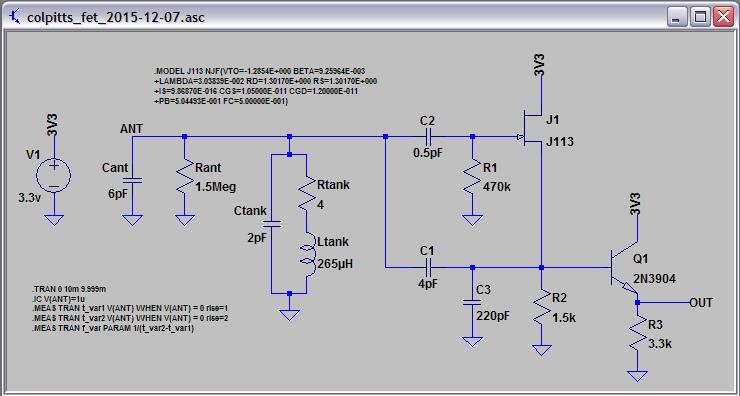
C1 is actually the antenna, the right side is the back driven shield, the left side is the front sensitive plate. Two 1pF caps in series form C2, it seems the gain here has a lot to do with stability. One might be able to stick this circuit close enough to the sensitive plate and forgo actual coupling via explicit capacitance, but I haven't tried that yet.
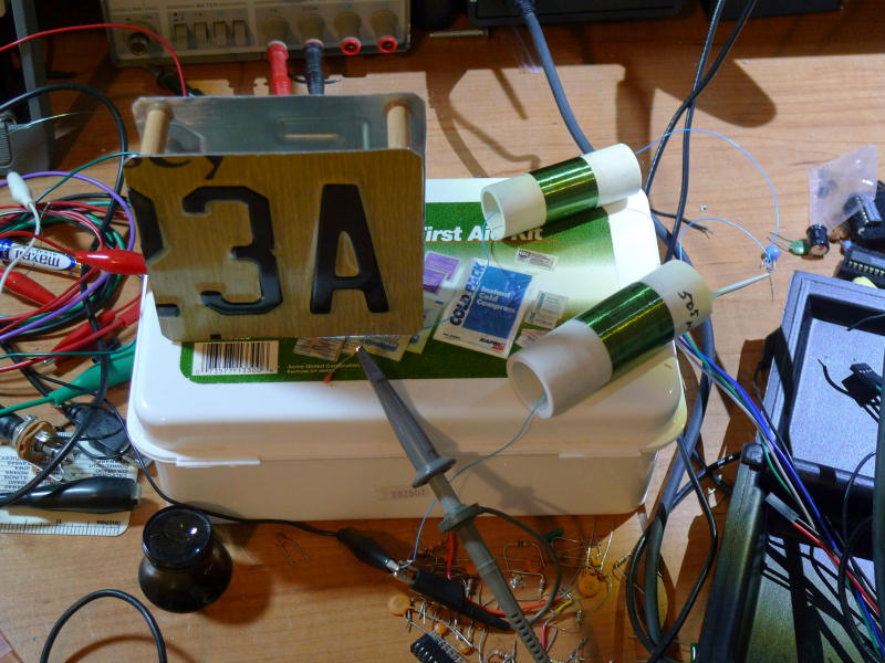
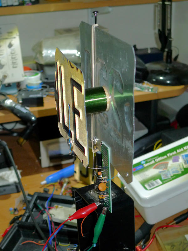
Here it is on my test setup:
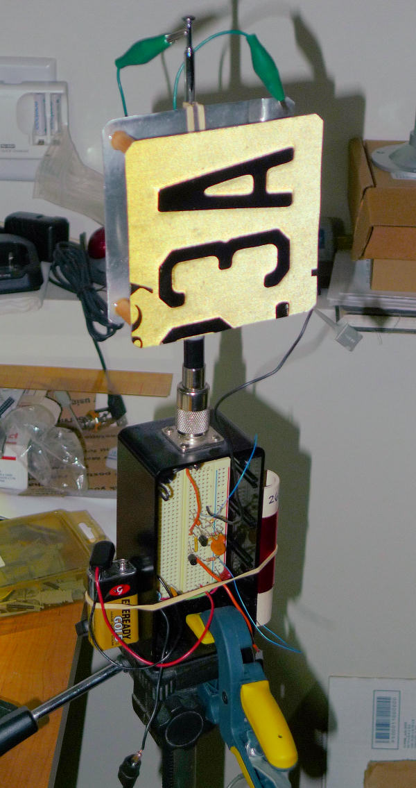
The resonant coil is on the right side of the project box, held on by the rubber band. It oscillates at 2.7 MHz, with ~40 Vp-p swing, and draws 1.9 mA from the 9V battery (including 3.3V regulator).
Spice file here: http://www.mediafire.com/download/63dev5zd9r6ifnb/colpitts_fet_2015-12-07.asc
Shield Drive C Sensor (continued)
Since the inductance is rather small, I thought it might be interesting to wind the coil on the spacer between the plates. The grounded end of the coil doesn't swing much voltage-wise in relation to the back shield plate (which swings 3.3V), and the resonant end of the coil swings exactly as the front sensitive plate does, so it's a natural. Locating the coil between the plates might provide a bit of electrical field shielding for the coil as well.
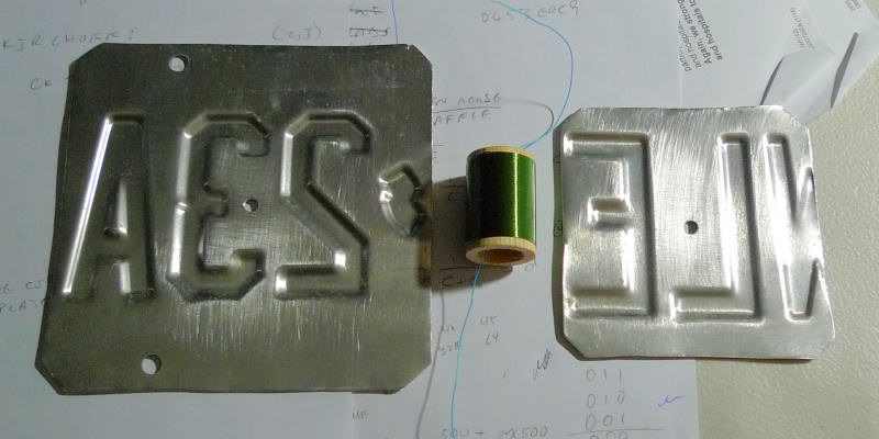
I had an old broken spring-loaded window blind out in the garage with a hollow wood dowel as the former, OD 25.7mm, ID 17mm. So I cut a piece 38mm long and put 148 turns of 32AWG on it, which when measures 310 uH, 6.2 DCR. I cut two plates from an old aluminum license plate, one 140mm square, the other 100mm square. I'm experimenting here with a larger shield to possibly make things more directional. Here they are before assembly:
I used 5 minute epoxy to glue them together and waited an hour or so before experimenting. Here is the assembly on my test setup:

I had to increase coupling from the front plate to the FET to 1pF to make it stable and to make the buffered output amplitude decent. It oscillates at 2.9 MHz with 30 Vp-p at the front antenna, and draws 2.1 mA from the 9V battery.
It seems stable, but I need to build the oscillator on a decent board and place it closer to the antenna. The question is where to best place it? It requires a direct connection to both front and back plates, so I'm thinking maybe between the plates, at the outer edge of the back plate.
Plate Linearity
One thing that really shocked me as a result of getting real hand & antenna mutual capacitance data was the very linear correspondence of capacitance to inverse hand distance for the plate antenna (slight pooping out near the antenna is likely due to the rectangular geometry I chose to test). So I again went to the academic capacitance papers and books available on the web, trying to find either a decently accurate formula for two disks, or tabulated data from some process proven mathematically to be accurate. If you read these papers you'll notice that the researchers are fond of incorporating "aspect ratios" into their calculations, because the results are identical if the physical configuration is scaled up or down in a certain way. This makes the solutions more generally applicable, but it also makes it more difficult to convert their findings into real hard numbers. The most down-to-earth paper I could find was "Form and Capacitance of Parallel Plate Capacitors" by Nishiyama & Nakamura, 1994. Table 2 in particular compares the results of a boundary element method (BEM, a kind of finite element analysis I presume) with two extremely simple 2-plate equations. Working backward through the aspect ratios, and things confusingly called capacitance that are really just multipliers, I was able to correlate their numbers with the simple equations.
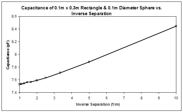
It turns out that total capacitance is very close to the trivial mutual capacitance equation you see in high school texts (C = epsilon0 * Area / distance between the plates) plus the intrinsic capacitance of the elements with the universe. Within 1% or so for larger distances, growing less accurate as the plate distance shrinks. This was a surprise to me, I expected the trivial equation to be more accurate the shorter the distance, but in fact it gets worse in this direction. And we are left with an almost perfect (for government work) linearity over the longer distances involved in Theremin play (say 2" to 3 feet for reasonably sized plate antennas). Here is a plot of perfectly calculated capacitance for two fist-sized plates (one the hand, one the plate antenna):
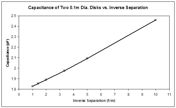
So the 1 on the x axis corresponds to the plates 1m apart, 10 is 100mm apart. These papers also talk about geometries getting pretty equivalent as distance increases, so the spherical-ish hand with a plate antenna should behave largely the same as two plates.
Anyway, if my Theremin had a pitch field as linear as the above curve I'd be quite satisfied I'd done my best. How might we convert the measured oscillator frequency or period into a number we can feed an analog or digital oscillator? Obviously by working backwards from the LC equation:
Two circular plates with radius r (m)
f = 1/p = 1/(2*pi*sqrt(L*Ctotal))
where L is the inductance (Henrys) of the coil
Ctotal = Cmutual + Cintrinsic = Cm + Ci (F)
Cm = Kc/d
where Kc = epsilon0*pi*r^2 (pF*m^2)
and d = distance between the plates (meters)
and epsilon0 = 8.8542 (pF/m)
Ci = 8*epsilon0*r (pF)
Taking the first equation and solving for Ctotal:
Ctotal = 1/(4*pi^2*f^2*L)
Expanding Ctotal and solving for d:
Kc/d + Ci = 1/(4*pi^2*f^2*L)
Kc/d = 1/(4*pi^2*f^2*L) - Ci = (1-4*pi^2*f^2*L*Ci)/(4*pi^2*f^2*L)
d = (4*pi^2*f^2*L*Kc)/(1-4*pi^2*f^2*L*Ci)
So we have an f squared term in both the numerator and denominator, and we have to do a divide or at least an inverse.
We can solve this for the measured period as well simply by plugging f = 1/p into the above result and multiplying top & bottom by p^2:
p = (4*pi^2*L*Kc)/(p^2-4*pi^2*L*Ci)
This looks a bit simpler: the numerator is a constant gain factor, and the 4*pi^2*L*Ci in the denominator is also a constant, which is set to the value of p^2 when the hand is at infinity.
=============
But we can't use the distance directly as input to a VCO. For one thing it is linear (which is fine if your VCO has an exponential response), for another it increases as the hand distance increases. What we really want is a number that decreases as the hand moves away from the antenna, and goes to zero (or some constant value) when the hand reaches the null point distance. We might as well incorporate variable sensitivity and overall pitch offset here as well.
Call dn the null distance. We want input factors alpha and beta as sensitivity and offset, respectively. The value (dn - d) gives us a directionally correct curve. Subtracting dn/2 lowers the curve to the x axis, whereupon we can multiply the sensitivity factor alpha, after which restoring it to the original position by adding dn/2. Finally we add the offset factor beta:
op = (dn - d - dn/2) * alpha + dn/2 + beta
op = (dn/2 - d) * alpha + dn/2 + beta
So for alpha = 1 we get normal sensitivity, for alpha = -1 we get reversed sensitivity (opposite pitch sense), and for alpha = 0 we get a constant tone of dn/2. We are making the hand vs. distance pitch curve "teeter-toter" about the mid point with alpha, and offsetting the bulk result with beta.
We can take this result (op) and use it as the input to the linear tuner. And we would need to do an exponential conversion on the result (op) in order to use it as the input to a linear VCO.
=============
It's interesting to think of the above processes in relation to the Theremini calibration procedure. For the period measurement, the denominator constant 4*pi^2*L*Ci is likely set to p^2 when you are told to stand far away from the Theremini.
I'm thinking of just presenting the user with 2 or 3 values that can be tweaked with feedback as to what is going during the tweaking process. Perhaps Ci, alpha, beta. With L and r buried in some submenu.
=============
You have to be really careful around physics types when they're using the term "capacitance". Sometimes they are talking about mutual, sometimes straightforward mutual + intrinsic, sometimes a weird mix of mutual + intrinsic, etc. For Theremin use one is usually most interested in the total C as seen by the coil, which is mutual + the intrinsic of the antenna (i.e. a weird mix).
Plate Linearity (cont)
Here is my 2-disk capacitance spreadsheet: http://www.mediafire.com/download/226w0ou33xdk90e/plate_capacitance_2015-12-11.xls
Here is the error of the simple equation according to the paper on which the spreadsheet is based (for 100 mm diameter plates):
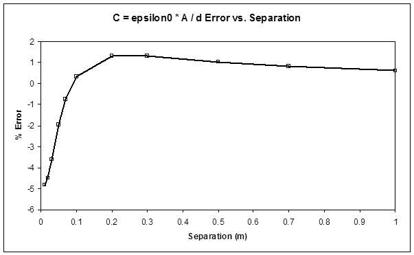
I take this to mean that the simple equation predicts mutual capacitance very well for larger separations, which is surprising because it is the the exact opposite of what one would expect ("accurate for small d" or similar invariably accompanies the simple equation.)
The only thing I can figure is maybe they're talking about total capacitance, not just mutual. But if you add in the intrinsic plate capacitance then the simple formula again works best at wide separations. Literally academic I suppose, as the error is negligible for Theremin distances & geometries, and even the capacitance formed by the drive and sense plates can be calculated via the simple formula with only a few percent error.
The paper contains a more accurate simple formula that is broken into two ranges of separation for those situations requiring greater accuracy on the low end.
Shield Drive C Sensor (continued)
I transferred the oscillator to pad-per-hole protoboard and affixed it to the back drive plate:

Here is a view of the assembly:
It oscillates at 3.43MHz, with a 38Vp-p swing on the front plate. Even at 50ms scope delay the 1.4Vp-p buffer output is very stable and the whole thing seems quite sensitive and directional.
Bought one of those 50V ceramic capacitor assortments off eBay for $6 / free shipping. 20 pieces of each value, 50 values from 1pF to 100nF, including 1pF, 2pF, ..., 9pF, 10pF:

Every budding Theremin builder should have these or similar in their kit. Some of the markings are faint, the leads could be longer, the little bags are hard to open if you don't know the trick, and the voltage could be higher, but all-in-all they're a pretty good deal. I spot checked some and they were within 10%.
In contrast, the resistor assortment offerings don't seem all that good, as they give you the same resistor count for all values (when you really want the most of the standard 1, 1.5, 2.2, 3.3, 4.7, 6.8, 10, etc. values) so you end up with a lot of weird ones. The metal film ones tend to be poorly marked. I may end up rolling my own kit, as some sellers will give you 100pc of any value for $1. 10ohm to 10meg would cost $37. It sure is strange being able to buy small quantities at near wholesale prices.
Shield Drive C Sensor (the end)
In an attempt to better understand the capacitance of multiple plates, hands, etc. I did another web search for tools that operate on this type of problem and stumbled across FastCap, part of a suite of tools which were written back in the early 90s: http://www.rle.mit.edu/cpg/research_codes.htm. There is a Win version off of that page: http://www.fastfieldsolvers.com/. The input is text based, with a GUI and some DOS helper apps to create meshed 3D structures. Been playing with it for a couple of days investigating various geometries and it looks as though the shield drive configuration is inherently low sensitivity, so I'm ditching it.
The output is a capacitive matrix that gives you a lot of info. One thing that surprised me (though looking back on it it shouldn't have) is that intrinsic capacitance of the antenna changes when mutual capacitance between the hand and the antenna changes. Charges on the conductors redistribute and everything changes, so you need a tool to tell you exactly what is going on. Intrinsic capacitance reduces with the approaching hand, which hurts sensitivity. Anyway, the most linear geometries that are also the most sensitive are large plates, say 0.2 meters square. A plate 0.1m x 0.3m is a close second and may be preferable as it is a more conventional antenna shape. I'm using a 0.1m diameter sphere as the hand model:
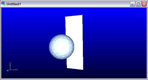
There's an 11.4% capacitance change (as seen by the inductor) over the 0.1 to 1.0 meter range. The FastCap program is quite nice!
[EDIT] I verified the FastCap results with values the paper I mentioned previously. Indeed, the results in that paper are based on boundary element methods (BEM) which is the basis of FastCap.
Spreadsheet: http://www.mediafire.com/download/sa4lesjaxxm5f3g/plate_capacitance_2015-12-17.xls
You must be logged in to post a reply. Please log in or register for a new account.