


Let's Design and Build a (mostly) Digital Theremin!
Posted: 2/21/2016 5:08:09 PM

Ya, it may seem like I'm off on a tangent (I'm actually off on a cosine ;-) but an efficient EXP2 is a must-have in order to implement the current (shifting sands of my) digital Theremin game plan.
Lots of nitty-gritty in the math libraries and floating point hardware everyone takes for granted. A lot to be learned there as well. When it comes to doing things the most straightforward way in the binary hardware of the processor, high level languages and compilers often paradoxically stand in your way. Reading this nearly made me weep:
http://foonathan.github.io/blog/2016/02/11/implementation-challenge-2.html
All those backflips for "portability" (ARM Cortex-M0+ has no CLZ hardware function!). If you ever wonder why your +4GHz 8 core machine often goes down for the count, read that article. Every coder does this kind of thing all the time these days - worse it's often in an interpreted scripting language. Retarded turtles all the way down.
With the right standard library, a bit of OO, and a little inheritence, C++ could have killed. Too bad it became the bloated, unwieldy monster it is now. Other languages don't seem to be much better, and few exploit the soul of the hardware as well as old school C does. Straight up bit manipulation is now regarded as an "unmaintainable, arcane art" god help us. Binary is where all the real action is.
Posted: 2/23/2016 6:22:07 PM
Needs More Cowbell Tank
Designers (the recent term "makers" turns me off as being overly Ayn Randian) tend to fall into ruts; we cling to tried-and-true comfort zones when it comes to circuits, so it's nice every once in a while to revisit old stuff after doing something completely different (algorithms in my case) with a clean pair of eyes.
I understand resonance and how it applies to Theremin tanks and oscillators much better now than when I started down this road. Some current observations / ramblings in no particular order:
1. Ping an LC tank and it will ring based on Q, which is governed by coil DC resistance (DCR) and any external resistances connected to the tank, because resistance turns electrical power into heat.
2. Some LC power is also lost due to RF emission, and I suspect the intrinsic capacitance of an antenna looks somewhat less than ideal mainly due to this (i.e. it is radiated away).
3. Repeatedly ping an LC tank at resonance and Q is the transfer voltage "gain" you get, which is most easily seen with the series tank configuration.
4. Parallel tanks require high impedance drive to maintain high Q, because the drive is at a high impedance point in the tank.
5. Series tanks require low impedance drive to maintain high Q, because the driver is interposed between the capacitor / coil return path.
6. Both series and parallel tanks require similar drive currents in order to maintain similar resonant voltage swings, and the magnitude of the current seems to be inversely proportional to the tank inductance value.
7. Parallel tank drive through a capacitance directly loads the antenna capacitance, whereas series tank drive through a low impedance driver on the other end of the inductor doesn't. Series tanks are therefore capable of higher absolute sensitivity.
8. Theremin operation at lower frequencies is problematic because the DCR of the longer finer wire generally required to wind larger valued L coils limits Q. (To a first degree, inductance is proportional to wire length, as is DCR.)
9. Using ferrite to make physically smaller coils with less wire is problematic because of the losses associated with AC magnetization of the core lower Q. Ferrite also introduces undesirable thermal dependence in the value of the coil (drift), though this can sometimes be traded off with the magnetic field concentration the ferrite core provides via precision air gaps or various ferrite formulations (and best of luck with that).
10. There are two good reasons you don't see a lot of JFETs in schematics, particularly in low voltage designs: a) The critical parameter VT - the cutoff voltage - is ill defined. b) They tend to have poor gain. Bipolar transistor turn on voltage is always around 0.7V and gain can vary but is usually guaranteed to be above some reasonable value. Now, sometimes you want a square law low gain and have the supply voltage headroom to properly linearly bias a JFET. And sometimes you need the high impedance gate input a JFET gives. The rest of the time a BJT will probably work as well or better, and will be easier to get your hands on and less expensive to boot.
11. High Q is generally desirable because it leads directly to higher antenna voltages, so the Theremin generated signal is much larger than external RF interference. This is a signal to noise (SNR) argument.
12. High Q gives better selectivity - external RF interference that differs in frequency from the Theremin generated signal is less able to interfere the larger the difference and the higher the Q. This is a signal to noise (SNR) argument.
13. High Q gives higher voltage swing with less drive current - high currents cause heating that can easily lead to drift.
14. Capacitive padding at the antenna directly leads to lowering of absolute sensitivity, but can sometimes raise the Q somewhat due to (I imagine) the lack of RF losses in the padding.
15. The phase response of an LC tank has a "phase gain" directly associated with Q. This is important if you plan on implementing a PLL with an LC tank as one of the elements in the loop, because total loop gain needs to be below 1 for stability. The phase gain peaks at resonance with a value of Q/pi, so this is what you have to design to. I won't show the calculations here, but it involves differentiating the formula that links phase and Q and normalizing it: phase(phi) = -tan^-1[Q(w/w0 - w0/w)].
16. If properly driven via a low impedance source, series tank frequency response to interference is the same as that of the parallel tank. Low frequency interference such as 60/50Hz mains fields gets coupled via the antenna intrinsic capacitance (~10pF) to the coil, and then to ground (or low impedance of the series driver). For both types of tanks, interference sees a bandpass filter to the rest of the circuitry with a correspondingly shaped impedance load. Adding series capacitance between the antenna and tank cannot improve SNR in this scenario, and may actually make it worse. There may be other reasons to add it, however, such as DC blocking, letting the antenna "float" to the earth field gradient, etc.
17. "Doubly resonant" designs like the Etherwave improve nearfield linearity by having a fixed frequency tank stimulate and respond to a variable frequency tank. Moving the fixed tank away from its center frequency causes it to have less response, to "poop out" as the hand approaches.
18. For various reasons the far field pitch response with any design will likely be non-linear, and coupling will only make this worse, hence the desirability of the ESPE01 and YAEWSBM decoupling modules. Pitch going to zero is by definition a huge non-linearity for a continuous logarithmic process or one based on ratios.
19. Antenna intrinsic capacitance is not fixed, but varies as the hand approaches and recedes. Think of one of those lightning balls:

When sitting alone, the discharges are evenly distributed spherically, but as a hand approaches the nearest discharges veer towards the hand. Same with antenna intrinsic capacitance, it is highest when the antenna is sitting alone, but decreases as a hand approaches. Decreasing intrinsic with increasing mutual cancel each other out to some degree unfortunately, lowering absolute sensitivity.
20. ALL oscillation is just loop gain in excess of 1 @ 360 degrees phase. The point of oscillation can easily not coincide with the LC resonance point, hurting Q. For stability, voltage swing, SNR, etc., delays in the oscillator loop have to be inventoried and watched like a hawk, particularly those which are temperature dependent (e.g. semiconductors, ferrite cores, etc.). Noise from resistors and active components can easily influence stability as well. In particular, large value resistors are noisy and have trouble driving capacitance in a snappy manner, so they can easily introduce huge delay when all you really want is voltage division with minimal loading. Output rise time or slew rate for a given load is also delay, and this, along with poor transport delay, is the reason you shouldn't use 74C or CD4000 devices in Theremin oscillators.
21. Another thing that can negatively impact Q is skin effect. This is where the AC current density in the wire forming the coil is greater near the outer surface of the wire than near the center core of the wire (a nice practical explanation may be found here - gotta love hams). Since the full cross sectional area of the wire isn't being fully employed for conduction, the net effect is that of a higher resistivity conductor. Skin effect starts kicking at low RF frequencies and can easily give you effectively double the measured DC resistance or worse at just a couple of MHz. Multi-stranded Litz wire is one way to increase skin area, though only below 1MHz or so. Another way obviously is to increase the diameter of the wire, though this doesn't utilize the copper efficiently. Between the air core inductor bulk size decreasing with the inverse square of frequency and skin effect increasing with the inverse square root of frequency, there is an island of optimality around 1 to 2 MHz that is unfortunately mostly shared with the AM broadcast band.
========
Given all the above, I'm gonna bore you with yet another tiny variant on stuff I've been posting for what seems like forever:
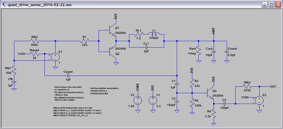
LTSpice file here: http://www.mediafire.com/view/we9sdeali4sdpie/quad_drive_sense_2016-02-22.asc
The series tank is superior for this application, and it requires low impedance drive for high Q. R1 is transformed at the emitters of Q1 & Q2 to R1/beta, where beta is generally around 100, so the left side of the coil "sees" around 2.2 ohms, which is below the DCR of the coil. R1 isn't necessarily a real component, it could be the impedance of an FPGA output pin or similar. The right side of the coil resonates with the intrinsic C of the antenna, and is knocked down 100:1 via C1 & C2, and buffered via R2-4 and Q3. I initially had a J113 JFET here but a 2N3904 works just as well and has more predictable behavior. Cquad, Rquad, E1, and all the stuff to the left is just there to sustain oscillation at resonance for the simulation, real stimulation would come from the FPGA. E2 is there to square up the output, and may end up being implemented inside the FPGA as well.
Note that Q1 & Q2 drop the input voltage extremes by 0.7V, so 3.3Vp-p in gives 2.1Vp-p drive. I'm seeing ~250Vp-p swing on the breadboard with a 582uH coil, so the Q is around 120 with a 10pF capacitor as dummy antenna. In the sim with a 330uH coil, the current drive through Q1 & Q2 is ~27mA peak, half sinusoidal, which seems rather troublingly high but is consistent with drive being inversely proportional to inductance. I'm seeing 7mA average current draw for the 582uH coil including 5v => 3.3V regulator and output buffer, and the transistors are cool to the touch. With only 1pF antenna padding for sensing, the absolute sensitivity should be just under the maximum theoretical.
At higher frequencies I suppose one could drive the input with a lower voltage bank FPGA output pin, such as 2.5V. This would result in ~1.3V drive at the coil and lower current through the transistors. I wish the AM band was located somewhere else.
Posted: 2/24/2016 5:24:12 PM
Sensitivity Revisited & EWS Pitch Antenna Capacitance
Revisited ways to characterize sensitivity again yesterday. The result must allow one to generate a real calculable capacitance, and must also represent a somewhat linear function (it's kind of a gain factor). After some thought it's clear that % change in C will lead you back to the experimental results, and C is largely linear over inverse distance, so this is what we use.
% delta C = 100 * 2 * (C1 - C2) / (C1 + C2)
This is the C difference over the C sum, and when we multiply by 2 it is the C difference over the C average. Multiplying by 100 gives us percent.
delta 1/D = 1/D1 - 1/D2
This is simply the difference of the individual reciprocals of the distances associated with the capacitances above.
Sticking it all together as a ratio:
Absolute sensitivity = [100 * 2 * (C1 - C2) / (C1 + C2)] / [1/D1 - 1/D2] (% delta C * m)
I'm not all that clear on the units, the capacitances seem to cancel giving a pure ratio over 1/m, so % meters? Whatever, it does work and you can work backwards to reality given this number.
- For a moderate sized plate (0.05m^2) the sensitivity works out to around 1.5 %m.
- For the EWS pitch tube antenna the sensitivity works out to around 0.796 %m (I just ran this through FastCap):
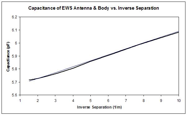
So the moral here for digital Theremin designers is this: don't use the EWS tube as your pitch antenna if you want maximum sensitivity (and linearity) - use a plate instead.
Absolute sensitivity characterizes raw capacitance at the antenna as seen by the LC tank, and not direct nor heterodyned frequency response (though you can obviously plug C change into to the LC equation to get those).
Posted: 2/29/2016 5:01:42 PM
dewster said: "So the moral here for digital Theremin designers is this: don't use the EWS tube as your pitch antenna if you want maximum sensitivity (and linearity) - use a plate instead."
As an engineer you may be disconnected from what is beautiful about an on stage theremin performance, it can be spiritual.
Also I really like your explanation in the 20 points above, I need to save that as a printout. The gas globe and capacitance is my favorite, I dare not mention RF energy as I use to get yelled at for bringing up EMR. In "my own theory" of why a good earth ground improves the sound of a theremin that uses two LC oscillators... is that the energy is always building and it needs to bleed off somewhere to avoid distortion in the RF wave shape which does partially transpose into the audio wave shape or at least mine.
Posted: 2/29/2016 6:47:13 PM
oldtemecula, you bring up a point that I have thought about to some degree.
Every once in a while I stand at my new prototype and try to "feel" the implications of the ergonomics. A large-ish plate antenna is likely as easy to play as a standard 3/8" rod antenna. It might actually be easier to play, as the plate is easier for the player to see, and thus easier to judge the distance between the pitch hand and plate. (I also like the way I can mostly keep my upper arms vertical and very near or touching my body, because it is the most comfortable and stable position IMO.)
Not sure what audiences might think of plate antennas, but that takes a distant second in my mind to optimizing things for the player, which like it or not calls for a plate. Form follows function and all that.
Posted: 2/29/2016 7:37:13 PM

dewster, how comes that the most linear theremins which are used by true professional musicians, like the EPro and the Henk prototype which Lydia played in the early nineties, have rod and not plate antennas?
Rupert Chapelle playing an Art Harrison theremin is for sure interesting for certain people but also for sure, it is very very far from being professional and representative.
I really enjoy your commitment to theremin research and design, but obviously you are missing an important factor : Regular contact and exchange with true professional thereminists and their instruments. You should have lessons with people like Lydia, Carolina and Thorwald, you should put your hands on all upper class theremin models which have been built and sold in the last 30 years. That takes an immense amount of time and money, but without that, you risk to miss the real target with your creative engineering.
Posted: 2/29/2016 9:35:45 PM
"... how comes that the most linear theremins which are used by true professional musicians, like the EPro and the Henk prototype which Lydia played in the early nineties, have rod and not plate antennas?" - Thierry
It all depends on the technology of your approach.
A thin rod is the best linearizing shape to use when generating audio pitch directly via baseband heterodyning.
A plate is the best linearizing shape to use when exploiting the fact that mutual capacitance (as seen by the antenna) is highly proportional to the inverse of distance (and calculating that distance by working backwards through the LC resonance equation). A plate also has around double the absolute sensitivity of a rod, something you don't care very about much when doing analog heterodyning, but something you care very much about when going the direct measurement route.
The target I'm aiming for hasn't been built yet, though I do agree that there are things to learn from the old masters and their creations.
Posted: 2/29/2016 10:41:10 PM
The Mummy's Enclosure's Curse
Theremin enclosures are a huge problem IMO. It's my feeling that way too many Theremins are built around a given enclosure, rather than vice-versa. For cost reasons the selected enclosure is usually too small, which gives cramped pitch and volume antenna spacing, and antenna heights that aren't optimal from a player's perspective. Unfortunately, it seems that custom cabinetry is called for in order to maximize the ergonomics of the design. I like the sideways 'C' of Theremin's later Theremins.
Posted: 3/2/2016 1:20:24 PM
Adding: maybe I've had Theremins on the brain for too long, but the ergonomics challenge that Theremins present seems fairly simple compared to other musical instruments. It boils down to what will the antennas and control surface look like, and how might they be optimally positioned for the player. In contrast, when designing a guitar there are a thousand ways to die. Tight tolerances for the fret placement, and nut / bridge placement and height for intonation, ease of playing, and elimination of buzzing; fingerboard and neck radius / thickness fitting the hand; body shape fitting the human body; not to mention things like overall tone and physical attractiveness. One little thing wrong can kill the whole deal. Tradition is something you often end up fighting and conceding to with guitars, whereas there is very little of that with Theremins. I suppose there is freedom in fewer expectations, but there are fewer guideposts as well.
You must be logged in to post a reply. Please log in or register for a new account.