NCPD
I'm taking another look at the digital generation of square waves for LC tank stimulus. Generating a precision variable lower frequency clock from a fixed higher frequency system clock is a fascinating area of study, and one I've nosed around in quite a bit. LC is nice because it acts like a low pass or band pass filter, thus strongly attenuating drive harmonics. LC also acts like a flywheel, so as long as the stimulus is correct on average (i.e. over several cycles) then individual cycle stimulus can be less than ideal - which it will be because we only have discrete system clock periods with which to construct the output cycles - the output transition points are fixed so they usually won't correspond exactly with the desired transition points.
The general approach is that of the phase accumulator or NCO (numerically controlled oscillator). Take an input number and on each system clock add it to a fixed width accumulator. The larger the input number the more often the accumulator will roll over. The MSb (most significant bit) of the accumulator is a square wave clock with frequency
clk_o = clk_i * freq_i / 2^n
where clk_i is the system clock, freq_i is the input number, and n is the bit width of the accumulator. The precision with which we can set the output frequency is set by the accumulator width, and it's fairly trivial to get PPM resolution just by using 20 or more bits. Lower frequencies can be accommodated with an integer divider afterward, which enables a decoupling of the carry chain for speed up.
The output will be best-effort in terms of phase error from the ideal. That is, the nearest system clock edge is used as the output clock edge. This may sound ideal, but in most cases it actually isn't because the output phase error can easily form low frequency alias patterns (limit cycles) that are impossible to deal with via filtering, even in our LC case. One way to break up patterns is to permanently set the LSb of freq_i to a 1, which keeps the lower bits of the accumulator active, and provides ~3dB SFDR improvement (spurious free dynamic range is the figure of merit here). An even more effective technique is to take the parallel output of the accumulator, add a small amount of dither noise (peak average amplitude >= than the value of freq_i) and use the MSb of this as the output square wave. Each new output edge triggers the noise generator to provide a new noise sample. Conceptually, what is happening here is we are statistically exposing the full accumulator value to the world. Using this technique one can produce square waves with high spectral purity, certainly with enough quality for digital Theremin use. Indeed this is exactly what my first prototype employed, in a DPLL configuration where the phase error was measured and used as feedback to adjust the frequency / phase.
So why look this dithered, LSb=1 style NCO gift horse in the mouth?
Well, one issue is the freq_i input is accumulated on every clock. This can be an asset, because variations in freq_i are then averaged over the entire cycle (this is a form of moving average or boxcar filter). But it also means this small number gets multiplied up by a factor of clk_i / clk_o, so if we are generating freq_i from a control process like the accumulator or low pass filter of a DPLL, it must be highly attenuated before use, which tends to throw away precision in the digital realm. Another issue is the dither noise should ideally vary between zero and the value of freq_i, which requires either multiplication, or the employ of a somewhat non-ideal fixed and larger noise level (though there are tricky and efficient ways to do the multiplication via a series of adds). A final issue is that we measure things like phase error by counting system clocks, which are therefore period rather than frequency based, which gives us a variable loop gain factor to worry about. It would be more direct if we could control the period numerically, rather than the frequency. How might we do that?
The obvious approach to a NCPD (numerically controlled periodic delay - my term for it) is to take the input period_i and count up to it from one, or load it into a counter and count down to 1. But how do we handle fractional periods, where e.g. period_i = 9.125? We could accumulate the fractional portions until the sum is >= 1 then extend the output period by 1 system clock and subtract 1 from the accumulator. This approach works but it is a bit fiddly if implemented as two parts. It gets even fiddlier if we dither it, and we definitely want to do so. Is there any way to more tightly integrate things?

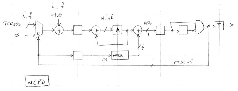
The above diagram shows where I am at the moment with a solution. The input is a fixed decimal with i integer bits and f fractional bits. This gets selected for one clock at each output clock edge, which adds the value, with the integer 1.0 subtracted from it, to the accumulator A. The rest of the time an input of zero is used, which gives us -1.0 as the input accumulator value, which decrements the integer portion of the accumulator value and leaves the fractional portion undisturbed. After this, noise is added and the MSb of the result is registered and the rising edge detected. This flag is used to toggle the output, to control the input multiplexer, and to generate a new dither noise sample.
What's so clever about it? First, the accumulator holds both the integer and fractional values, which lets the accumulated fractional portion naturally carry out into the integer portion. Second, it's a closed-loop "leaky bucket" implementation, so the input accumulation can happen at just about any point and it will still function correctly long-term, which allows us to perturb an individual period without affecting the next, we can employ roll under detection (MSb going from zero to 1) to sense when to accumulate period_i, and we can inject noise without slowing things down. Third, the optimal dither noise width is fixed (the same bit width as the accumulator fractional width) so we don't need multiplication in order to scale it. Fourth, there is a bit of magic that can be applied to the noise generator which gives us an approximately differentiated output with one clock per sample almost for free (I'll describe this in a future post).
Using a fairly deep pipeline here really speeds things up (>300MHz system clock limited to max 250MHz net toggle rate in the target device). It also limits the smallest input period value, though that doesn't really matter as we will be using the NCPD to synthesize square waves with many tens of system clocks per period.


