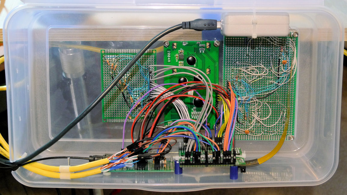
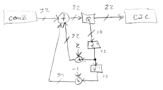
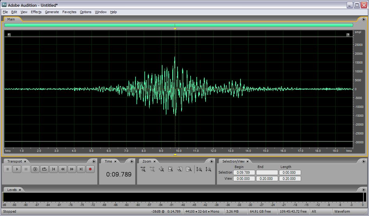
Via snippets of Hive assembly, I've verified that all the hardware is functional.
The digital conditioning of the rotary encoders in particular is interesting: I take the clockwise and counterclockwise inputs, resync them (shift registers), and invert them. This gives a two bit Gray code, which I convert to a two bit binary code via XOR. From there it's easy to check for the next clockwise state (+1) or counterclockwise state (-1), with full count up or down from and to the detent state causing a corresponding clear-on-read bit to light up in the Hive encoder register. It works really well, I don't see any glitching or missed rotation events. The carry chain is often your most efficient decode. Each pushbutton on each encoder is similarly given a clear-on-read delta bit for when it changes, as well as a bit that is lit as long as it is pressed. The pushbuttons do show a bit of bouncing, but very little as these things go.
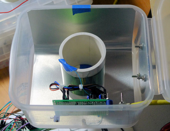
I'm seeing what is probably USB 5V droop at the LED tuner, with the red octave LEDs in series (1.7V * 2 = 3.4V) most affected by being modulated with gross circular note display activity. Not sure how important this is. I don't see a lot of pitch oscillator disturbance with the note LEDs cycling, but I do see some with the octave digits, which is understandable. Not sure how important this is either.
I stuck a power toggle switch on the side of the control case so I wouldn't wear out the USB connection power cycling it. I also ordered a 3 meter USB2 extension cable which should arrive tomorrow.
===========
Today I investigated the use of the approximation d = 1/C for Theremin pitch and volume values in an Excel spreadsheet.
Working backwards from the LC resonance equation:
F = 1 / [ 2 * pi * sqrt( L * C ) ]
Substituting in d = 1/C, Cinf as the antenna intrinsic C, and Kc as the "gain" of the hand capacitance with distance, we get:
d ~= F^2 * 4 * pi^2 * L * Kc / [ 1 - ( F^2 * 4 * pi^2 * L * Cinf ) ]
If:
K1 = 4 * pi^2 * L * Kc
and
K2 = 4 * pi^2 * L * Cinf
we get the form:
d ~= F^2 * K1 / [ 1 - ( F^2 * K2 ) ]
Multiplying through by K2, and setting K3 = K1 / K2, we get:
d ~= F^2 * K3 / ( K2 - F^2 )
Clearly, K2 will be set to be a bit larger than F^2 when standing away from the Theremin. And K3 is a general gain factor.
To get an operating point number that gets larger as the hand approaches the pitch antenna, we subtract d from a number that is the value of d when we are standing at the playing position with our pitch hand retracted. To generalize this we can make K3 negative, which makes d negative, so we simply add d to this new factor. What is the form of this new factor? We want changes to a new control K4 to translate or move the entire response up and down, so it is an offset. We also want changes to the gain control K3 to "rotate" the response about some middle point without translation. This gives independent control over playing range and sensitivity. With a negative K3, the graph of the line is negative sloping from zero, so we want to pull the line up to the origin at the middle point, and this is accomplished by adding -K3 * K4 (i.e. by adding a scaled translation value) to the response. The final translation up is simply adding K4:
translation factor = -K3 * K4 + K4 = K4 * ( 1 - K3 )
So the final form is:
Pitch (linear) = [ F^2 * K3 / ( K2 - F^2 ) ] + [ K4 * ( 1 - K3 ) ]
Which we can feed directly to a linear response pitch display and to an exponential response oscillator or NCO.
Interestingly, with proper adjustments to everything, linearity doesn't seem to be affected by the removal of F^2 from the numerator. But having it there probably helps normalize things.
Also, the above will work for the volume side, where we want the volume number increasing as we withdraw our hand, by simply making K3 positive and K4 negative.
