What's the Frequency (Kenneth?)
Trying to put internal pitch numbers to bed. There's a lot to consider in this seemingly simple exercise, such as maximum oscillator / filter frequency, what gets aligned to what, tuner pickoff point, pitch alignment to the real world (tuning), and hardware induced offsets.
Some basics:
1. The linear pitch number itself is an unsigned 32 bit integer with fixed 5.27 decimal place. The decimal location is naturally given by the EXP2 function, which takes a 5.27 as input and gives a full unsigned 32 bit output (5 bits give a 32 bit shift). So the upper 5 bits give us the octave, and the lower 27 bits are obviously the fractional octave. Running this through EXP2 gives us the exponential pitch number for use with oscillators and filters.
2. Maximum possible pitch with an Fs (sampling frequency) of 48kHz is Fs/2, or 24kHz.
3. There is sub-note quantization going on within the pitch corrector, and also within the tuner display, so aligning the pitch representation with integer note values seems worthwhile.
4. Translating the pitch number to an actual frequency and displaying it accurately means we have to align things with the standard A4 = 440Hz.
5. We need 2^12 the PCM rate for the SPDIF logic clock, but there are limits to the hardware PLL in the target FPGA, and the closest we can get with the stock demo board oscillator is 50MHz * 59 / 15, or +298.4 ppm (~+2 cents; under ideal circumstances the human ear can hear maybe 3 cents of error.)
6. I can't hear Fs / 2 = 24kHz, and I can just barely hear Fs / 4 = 12kHz (though my ears are getting kinda old) so oscillators could be limited to Fs / 4. Certainly the center frequency of filters don't need to go much higher than this either as there isn't a lot of point in altering harmonics that we can't hear. In fact, we could probably set the upper limit somewhat lower and no one would really notice or care. And the lower we set it the less trouble we'll have with aliasing.
7. The pitch side has an offset adjustment as part of the linearity calculations which can be used to move the pitch number around. It comes before the gain (sensitivity) adjustment so it can vary in strength, but it can be employed for rough global pitch offset with respect to hand location.
Previously I was taking up all the slack and weirdness at the tuner, dividing the oscillator frequency inputs by 4, and the filter frequency input scaling rather naturally included a divide by 4. But that gets complicated really fast, so I had to rely on a spreadsheet to track what was going on, and had to waste a lot of time coming back up to speed every time I worked on it. And it basically broke when I added pitch offset and sub-note quantization.
The method:
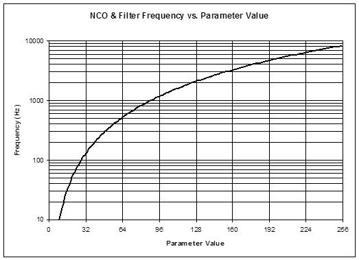
I'm picking C9 as the maximum frequency, which aligns the subnotes and the notes (i.e. the entire octave fraction). This is 8.372kHz which may seem kind of low at first glance, but sounds pretty high to my ears. The linear pitch number for this is the maximum 0xFFFFFFFF + 1. The 5.27 octave value is 0, so we have to add 9 inside the tuner, or 0x48000000, for it to display the octave number correctly. Note that the tuner octave display is hex, so it's modulo 16, even though there are 32 octaves in our 5.27 standard.
To make our oscillators generate the C9 frequency of 8.372kHz, we work backwards through the NCO phase accumulation at 48.014kHz, and the EXP2 function. At maximum input the EXP2 function conveniently returns essentially the same maximum output, so it can be ignored, and it then also conveniently cancels with the phase accumulator modulo, so it too can be ignored. The NCO equation is:
F_out = K_nco * Fs * F_exp / accum_modulo ~= K_nco * Fs * F_lin / accum_modulo
8.372kHz = K_nco * 48.014kHz * (2^32) / (2^32)
K_nco = 8.372kHz / 48.014kHz = 0.174365; or 0x2CA32F85 as a 32 bit unsigned fraction.
And since the filter inputs naturally divide by 4, we multiply this by 4 to get the filter constant K_filt:
K_filt = 4 * K_nco = 4 * 0.174365 = 0.69746; or 0xB28CBE13 as a 32 bit unsigned fraction.
So we've normalized both linear and exponential frequency busses by declaring the maximum value on them to be the note C9. And we conform with standardized A440 pitch inside the tuner with a 9 octave addition to the linear bus value, and inside each oscillator / filter with a fractional multiply to the exponential bus value.
Signal routing:
Here is the way I currently have the pitch side signal flow:
pitch antenna => linearization => offset & gain => (tuner tap) => pitch correction => (tuner tap) => cent, note, octave offset => (linear bus) => EXP2 => (exponential bus)
The two tuner taps let me observe either the pre- or post-quantized pitch. Global pitch offset happens after this so as to offset the actual pitch rather than the observation of it, after which it is exponentiated and fed to the various oscillators and filters.
===========
ByteBlaster Blues (you made me cry)
While modifying things I pulled the USB connection on the Altera USB Blaster (FPGA JTAG pumper) and almost had a heart attack when I turned the prototype back on, met with what looked like a huge drain on the power (very dim LCD backlight, dim LED tuner). Thinking I shorted something out during the latest mod I looked in vain for the issue. Plugging the USB Blaster back in restored all the brightness. So I was thinking maybe the USB serial port wasn't supplying sufficient power, and perhaps the USB Blaster was providing some? Turns out there is an errata concerning power cycling the USB Blaster target board and the USB connection to the USB Blaster. Altera (now Intel) says you can burn up the programmer by yanking the USB connection, though to me it seems likely you could also easily burn up the target with that kind of power draw. Idiots. Things they should be telling you up front... (and things they should have foreseen during the design phase)


