Let's Design and Build a (mostly) Digital Theremin!

Posted: 1/7/2018 5:27:45 PM
dewster

From: Northern NJ, USA

Joined: 2/17/2012

Hi-Lo 2: Circling the Square

Raising a [0:1) ramp to a power gives a nice concave curve over the same interval.  A rising and falling [0:1:0] ramp (triangle) over the same interval gives a double scoop with a point in the middle.  If you flip the second half upwards you get a nice continuous [0:2) "sinus" function that we can divide by 2 (right shift once) to get it over the [0:1) interval.  If we subtract the initial ramp from this, where the initial power is 2, we get something that looks remarkably like a sine wave (a second order polynomial approximation of it, arrived at accidentally).  If the initial power is greater than 2 we get the familiar looking glottal wave of Hi-Lo, but without using the sine subroutine!  And we can play the same powers scoop out game afterward to reduce the low frequency content:

I haven't tried this on the prototype yet, and it has more amplitude variation with the various settings, but it is an interesting and computationally inexpensive way to get adjustable controlled harmonic content without trig functions.

[EDIT] I can't figure out a straightforward way to get odd harmonics from it, so I'm sticking with the original Hi-Lo sine mutate.

[EDIT2] My headphone amplifier, a PreSonus HP4, literally burned up yesterday while we were out of the house (!). Whole downstairs smelled strongly like burned phenolic. Opened it up and one of the quad op-amps was charred, the PC board under it browned, and a nearby filter cap was bulging (presumably due to the heat).  Unsoldered the bad stuff and it still smoked when I plugged it in. Turns out a trace was somehow shorted to ground, so I clipped that and I'm back in business, but with one less output channel.  I'd like a reason to replace the HP2 actually, it has way too much gain IMO.

Posted: 1/9/2018 11:17:48 PM
dewster

From: Northern NJ, USA

Joined: 2/17/2012

Tuner Update

The 1" 7-segment common anode red LED display (KYX-1106BS) I ordered several weeks ago from HK arrived today.  So I just had to tear the old octave display out and install this new one.  In the process I added a 4 blue LED volume bargraph enhanced with PWM (pulse width modulation - used for the rest of the display which yields a nice smooth gray scale).  This completely consumes all 24 serial LED driver outputs (TLC5916):

The 7-segment could be brighter I suppose but it will do.  And I would have aligned it vertically with the other two displays, but the IC was in the way and I didn't feel like tearing it off the board just to move it.

The volume bargraph steps are 6 dB per LED, and this is using the linearized volume number rather than output volume.  I wanted it to reflect left hand height and active volume zone more than actual volume.

Also demonstrated is true chromatic pitch correction with variable quantization strength and variable second order low pass filter time constant.  I've got the strength turned up here more than normal (for me) so the action is rather exaggerated.  Static and slower movements gravitate to the chromatic scale, whereas vibrato isn't attenuated, and other types of faster pitch change are smooth and continuous.

With the crazy extended cold snap we've had lately, and all the dryness caused by raising our house temperature without doing anything about the reduced relative humidity, I've noticed several ESD event when touching the knobs (obvious reset of the menu and stack errors flagged in the processor error register).  So while I was under the hood working on the tuner I ran ground wires to the encoder bodies (which otherwise just float).  I should probably make some kind of safe bleed-off pad that I can touch and safely drain off any HV my body is charged to.  Several resistors in series to make 1M or so.

Posted: 1/10/2018 9:18:05 PM
dewster

From: Northern NJ, USA

Joined: 2/17/2012

What's the Frequency (Kenneth?)

Trying to put internal pitch numbers to bed.  There's a lot to consider in this seemingly simple exercise, such as maximum oscillator / filter frequency, what gets aligned to what, tuner pickoff point, pitch alignment to the real world (tuning), and hardware induced offsets.  

Some basics:

1. The linear pitch number itself is an unsigned 32 bit integer with fixed 5.27 decimal place.  The decimal location is naturally given by the EXP2 function, which takes a 5.27 as input and gives a full unsigned 32 bit output (5 bits give a 32 bit shift).  So the upper 5 bits give us the octave, and the lower 27 bits are obviously the fractional octave.  Running this through EXP2 gives us the exponential pitch number for use with oscillators and filters.

2. Maximum possible pitch with an Fs (sampling frequency) of 48kHz is Fs/2, or 24kHz.

3. There is sub-note quantization going on within the pitch corrector, and also within the tuner display, so aligning the pitch representation with integer note values seems worthwhile.

4. Translating the pitch number to an actual frequency and displaying it accurately means we have to align things with the standard A4 = 440Hz.

5. We need 2^12 the PCM rate for the SPDIF logic clock, but there are limits to the hardware PLL in the target FPGA, and the closest we can get with the stock demo board oscillator is 50MHz * 59 / 15, or +298.4 ppm (~+2 cents; under ideal circumstances the human ear can hear maybe 3 cents of error.)

6. I can't hear Fs / 2 = 24kHz, and I can just barely hear Fs / 4 = 12kHz (though my ears are getting kinda old) so oscillators could be limited to Fs / 4.  Certainly the center frequency of filters don't need to go much higher than this either as there isn't a lot of point in altering harmonics that we can't hear.  In fact, we could probably set the upper limit somewhat lower and no one would really notice or care.  And the lower we set it the less trouble we'll have with aliasing.

7. The pitch side has an offset adjustment as part of the linearity calculations which can be used to move the pitch number around.  It comes before the gain (sensitivity) adjustment so it can vary in strength, but it can be employed for rough global pitch offset with respect to hand location.

Previously I was taking up all the slack and weirdness at the tuner, dividing the oscillator frequency inputs by 4, and the filter frequency input scaling rather naturally included a divide by 4.  But that gets complicated really fast, so I had to rely on a spreadsheet to track what was going on, and had to waste a lot of time coming back up to speed every time I worked on it.  And it basically broke when I added pitch offset and sub-note quantization.

The method:

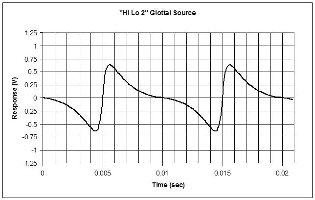
I'm picking C9 as the maximum frequency, which aligns the subnotes and the notes (i.e. the entire octave fraction). This is 8.372kHz which may seem kind of low at first glance, but sounds pretty high to my ears.  The linear pitch number for this is the maximum 0xFFFFFFFF + 1.  The 5.27 octave value is 0, so we have to add 9 inside the tuner, or 0x48000000, for it to display the octave number correctly.  Note that the tuner octave display is hex, so it's modulo 16, even though there are 32 octaves in our 5.27 standard.

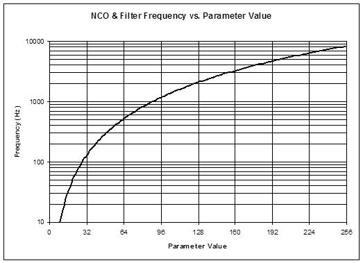
To make our oscillators generate the C9 frequency of 8.372kHz, we work backwards through the NCO phase accumulation at 48.014kHz, and the EXP2 function.  At maximum input the EXP2 function conveniently returns essentially the same maximum output, so it can be ignored, and it then also conveniently cancels with the phase accumulator modulo, so it too can be ignored.  The NCO equation is:

  F_out = K_nco * Fs * F_exp / accum_modulo ~= K_nco * Fs * F_lin / accum_modulo

  8.372kHz = K_nco * 48.014kHz * (2^32) / (2^32)

  K_nco = 8.372kHz / 48.014kHz = 0.174365; or 0x2CA32F85 as a 32 bit unsigned fraction.

And since the filter inputs naturally divide by 4, we multiply this by 4 to get the filter constant K_filt:

  K_filt = 4 * K_nco = 4 * 0.174365 = 0.69746; or 0xB28CBE13  as a 32 bit unsigned fraction.

So we've normalized both linear and exponential frequency busses by declaring the maximum value on them to be the note C9.  And we conform with standardized A440 pitch inside the tuner with a 9 octave addition to the linear bus value, and inside each oscillator / filter with a fractional multiply to the exponential bus value.

Signal routing:

Here is the way I currently have the pitch side signal flow:

  pitch antenna => linearization => offset & gain => (tuner tap) => pitch correction => (tuner tap) => cent, note, octave offset => (linear bus) => EXP2 => (exponential bus)

The two tuner taps let me observe either the pre- or post-quantized pitch.  Global pitch offset happens after this so as to offset the actual pitch rather than the observation of it, after which it is exponentiated and fed to the various oscillators and filters.

===========

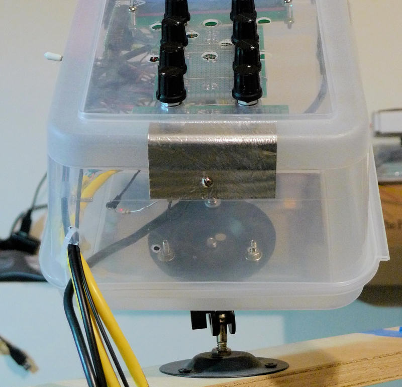
ByteBlaster Blues (you made me cry)

While modifying things I pulled the USB connection on the Altera USB Blaster (FPGA JTAG pumper) and almost had a heart attack when I turned the prototype back on, met with what looked like a huge drain on the power (very dim LCD backlight, dim LED tuner).  Thinking I shorted something out during the latest mod I looked in vain for the issue.  Plugging the USB Blaster back in restored all the brightness.  So I was thinking maybe the USB serial port wasn't supplying sufficient power, and perhaps the USB Blaster was providing some?  Turns out there is an errata concerning power cycling the USB Blaster target board and the USB connection to the USB Blaster.  Altera (now Intel) says you can burn up the programmer by yanking the USB connection, though to me it seems likely you could also easily burn up the target with that kind of power draw.  Idiots.  Things they should be telling you up front... (and things they should have foreseen during the design phase)

Posted: 1/11/2018 5:28:13 PM
dewster

From: Northern NJ, USA

Joined: 2/17/2012

Squared Exponential Parameters

Made a chart that tells me what the NCO or filter frequency is given the squared parameter on the LCD screen:

Squaring works well here as it gives access to the lowest frequencies without hurting the resolution and linearity of the mid and upper frequency points too much, and it keeps us from having to call the rather expensive EXP2 function.  Win-win.

[EDIT] Just ordered a couple of Microchip 25LC1024 1 Mbit SPI Bus Serial EEPROMs from eBay.  Looks like a drop-in replacement for the Winbond W25Q80BV SPI FLASH I bought a while back from Adafruit.  Easier to program (no need to erase first), small pages, withstands 10x more writes, data retention >200 years.  Should be able to fit several software loads and all parameter presets in there with plenty of room to spare.  The SPI SystemVerilog module I wrote is hanging off the processor bus and has been successfully tested with the Winbond device, which is socketed in the prototype but otherwise unused at this point.  Need to implement a preset system and some kind of bootloader...

Posted: 1/16/2018 7:51:23 PM
dewster

From: Northern NJ, USA

Joined: 2/17/2012

SPI Flashin'

Added some code to the Hive simulator that kicks out a TTL (TeraTerm scripting Language) text file which, when executed in TeraTerm, uploads (via RS232) the assembled software load and programs it into the SPI Flash.  The first 32 bits are the load length, the last 32 bits are the CRC32.  I'm using the 'wr' HCL (Hive Command Line interface) instruction to do a register write to the SPI SystemVerilog serializer / deserializer component hanging off the processor.  Upload and programming of ~16kB @ 230400 baud takes around 50 seconds, which is roughly comparable (once you've done it several hundred times) to an FPGA memory image update and re-pump (getting FPGA pumping out of the software update process is a high priority).  Since the thread managing the command line (7) also handles the LCD display and encoders, and the receive side of the UART isn't FIFO buffered, the script disables the interrupt during upload to avoid receive errors.  I've spot checked the programmed data in the SPI Flash and it seems OK, but I need to run a CRC over the entire thing to make sure.

One issue that complicates this whole mess is the idiotic big-endianness of the SPI Flash device.  It normally deals in bytes (which are endian agnostic, though its serial ports want MSb first) but addresses are 3 bytes and it wants the most significant one first.  The processor is little-endian (as god intended) though I gave it an "OP_SWP" opcode that endian swaps the bytes.  The actual CRC32 value is also dependent on the endianness of the data fed to it in 32 bit chunks.  Consistency is everything, so I'm thinking of writing a subroutine interface or two that make the SPI Flash look little-endian to the rest of the code.

Wasted a lot of time yesterday re-researching CRC32 as my spreadsheet values were't jibing with the various lame/cryptic/useless examples I could find on the web.  Turns out that was an endianness thing too.  I believe software types love big endian mainly because it takes things as we type them, and numbers are typed big end first.  But it's no way to organize processor memory, where the little end should have a smaller index value (address) than the big end.  With little-endian you never have to answer the question "little end of what?" as you do with big-endian, because the little end always refers to the same bit, nibble, byte, etc. regardless of the data type width.  And that, boys and girls, is why variable aspect ratio memories, such as those in FPGAs, are always little-endian.  

("Big-Endian Can Byte Me!" would make a great nerd t-shirt.)

[EDIT] Made a new "ws" (write SPI) HCL command that takes a 32 bit value and jams it at the SPI Flash: image upload time reduced to 15 seconds!

Posted: 1/18/2018 12:41:29 AM
dewster

From: Northern NJ, USA

Joined: 2/17/2012

Boot Loadin'

Just hit an embedded milestone, my first successful bootload!  Bootloader code is often in ROM, in this case I've got it located at the top of the 16kB address space, along with the subroutines it relies on.  So at boot, all threads except 7 vector to 0x3fff, which contains a halt instruction (spin loop).  Thread 7 goes to the boot_load routine at 0x3e00.  Here it checks a local flag to see if it has warm booted in the past.  If so it vectors to the normal beginning of thread 7 routines.  If not it sets the flag and reads the SPI Flash load and calculates the CRC.  If the CRC is bad it vectors to the normal beginning of thread 7 routines.  If the CRC is OK it copies the load to memory (stopping short of the top region it's occupying) and resets the threads.  Then the whole thing starts over.  It's a little tricky keeping the boot code and boot state separate, and tracking the warm and cold boot state.  The FPGA load itself acts like a ROM at start-up so that helps, and the boot code and fall-back code entry points (data and subroutine addresses) should naturally track as they are assembled and pumped together, though I imagine some kind of fixed location jump table in lower memory might help with keeping future updates more in sync with older boot loads.

So I can now just fire up the simulator, which assembles the code and generates the hive.ttl script, run the script in TeraTerm, do a power cycle, and I've got a new load up and running in under 30 seconds.  No need to fart around with the ByteBlaster anymore unless I want to change the boot code or the basic memory partitioning.  From a production standpoint the prototype is now both factory and field upgradable.  Free at last, free at last!

Posted: 1/18/2018 6:09:22 PM
dewster

From: Northern NJ, USA

Joined: 2/17/2012

Future Proofin'

Boot loading is like a time travel movie: it's all too easy to get caught in a loop, and it's difficult to think about and therefore avoid said loops.  You can have old boot code with a new SW load in the Flash, and vice-versa, so references between them need to somehow always work no matter what.  The goal therefore is to absolutely minimize cross references that require synchronization across all SW and boot loads, with zero being the ideal here.

I realized this morning that I could convert the boot loader to a subroutine, then return from it regardless of whatever happens there, which obviates the need for: 1) a warm boot; 2) a warm boot flag to keep the boot load process from looping; and 3) the need for the boot loader to know the beginning address of thread 7 code.  The boot loader subroutine calling address is nailed down with an explicit label assignment, and, as usual, the subroutine return address is automatically provided by the subroutine calling mechanism.  I also realized that the assembly scoping and include mechanisms allow me to encapsulate local copies of the various SPI subroutines in the boot loader subroutine itself, so there's no need for jump tables in the normal program space nor the boot code space.  Voila!  One explicit tie and zero implicit ties (addresses, calls, etc.) between the SW load and the boot code!  And no state associated with the boot process!

Of course this bit me in the ass first time I messed with it.  I pumped the FPGA up with the cunning new boot plan code, after which it promptly ran to the SPI Flash and loaded the old incompatible load, which bricked things and killed the UART port.  Hmm.  Suddenly it's clear to me why many programmable items implement a "hold down these two buttons you would never normally press during power-up to enter this special mode" deal.  So I added a check for a push button being depressed during power-up, which bypasses loading from the SPI.  I placed the check after the SPI load CRC check so as to give the button pull-ups time to pull them up.  It works!  If button 7 is pressed thru power-up then the software load will match the boot load, which guarantees correct inter-operation.

With all this going on, boot times appear to be slightly longer than they were before.  I have a huge 0.75 second delay at the beginning to allow the LCD to wake the hell up (and to allow the DPLL oscillators to stabilize) which I could probably make a bit shorter.  Still, it's under 2 seconds total, nothing like waiting for our digital pianos to rise and shine.

Posted: 1/20/2018 1:32:44 AM
dewster

From: Northern NJ, USA

Joined: 2/17/2012

ESD Bleedin'

When I was working on the control box I added a piece of aluminum tape to the outside bottom corner of the encoder area:

This is a bleed-off point for any charge on my body.  I touch it before touching the encoders, which as I said earlier now have a ground wire running to their otherwise floating shafts.  This ESD pad is connected to ground via two 470k resistors in series, making 1M total. Why not just ground it?  You don't want big jolts of voltage / current entering the system because no ground is perfect, and large slugs can cause fairly scary levels of "ground bounce".  And you don't want to get shocked if you can help it :-).  1M bleeds it off pretty quick, and you don't even feel it.  I haven't had an ESD event since I grounded the encoders (processor reset / flipping out / errors in the error reg), but a dedicated ESD bleed pad is something all Theremins should have IMO. 

I've read that thick film and carbon resistors are the best here, thin film can't stand as much over-current/voltage.  And you have to be careful how you do ESD grounding, you don't want it smacking other stuff down the line, so direct grounding to the lowest impedance point is best.

When I was gainfully employed, I remember lots of voodoo associated with ESD PWB layout.  We had a human body model spark gun, and one of the requirements was that the processor could flip out but would have to recover on its own without a power cycle. On one card it turned out the status LEDs, as seen through holes in the faceplate, were the most vulnerable to ESD. I suppose I need to put a watchdog of some sort in Hive, though none are perfect, and they tend to get in the way during development.

Posted: 1/23/2018 5:03:57 AM
dewster

From: Northern NJ, USA

Joined: 2/17/2012

EEPROMin'

The Microchip 25LC1024 EEPROMs arrived in the mail today.  Got them off eBay from Portugal, shipping was actually cheaper than from inside the US, go figure.  Increased one number, the SPI clock high / low time value in the Hive SV package, to accommodate the lower max clock frequency (50MHz for the old Flash part, 10MHz for the new EEPROM), recompiled the FPGA, pumped it, and I'm back in business.  It uses the same codes and procedures for reading and writing, and I can't say I notice any difference in terms of boot times.  Probably the best thing about this EEPROM is you don't have to erase it to reprogram it, you can overwrite a single byte in a page and the rest of the data remains, and it's reprogrammable at the 256 byte page level, rather than the 4KB block level of the Flash part.  Should be much more straightforward to store both program images and parameters in there.  So I guess it's time to come up with some kind of plan for instrument presets.

Posted: 1/25/2018 6:49:50 PM
dewster

From: Northern NJ, USA

Joined: 2/17/2012

Linear Domain Filtering

On my third try to put some kind of velocity response on the volume side.  A Thereminist I know knows Pamelia Stickney/Kurstin, and she does an interesting walking bass via Theremin:

Speaking volume is really low, but from the video above it's clear she's getting the attack by quickly closing her hand.  Her hand movement for the decay is more subtle and only clear when she turns the Theremin sideways - it's a slow movement towards the antenna after the attack.

Someone at TW recently posted a video demonstrating an attack circuit, but I can't find it now.  I wonder if there is anything going on in her EWPro that's enhancing the effect?  I spent much of yesterday analyzing the EWS volume circuit in LTSpice, but didn't find anything that manipulates the attack / decay in that manner (LM13600 first stage seems to be an inverting level shifting diode, second is the VCA).

Anyway, I'd like to add some sort of attack / decay to the prototype but the things I've tried so far don't seem all that useful.  One thing I ran into yesterday is where to locate it when conventional IIR/RC filtering is going on.  I think that sort of manipulation should be on the exponential side of things, rather than the linear side.  The linear side should be more like constant integration. Otherwise you get a double exponentiation, one from the filter decay and one from the EXP function.  This makes me wonder if I should not be using conventional low-pass filtering with the pitch correction, but simple integration instead.

It doesn't seem like the attack should work both ways, that is by turning the volume on and off quickly.

[EDIT] Yarg!  Giving up on it for the third time.  It just doesn't seem all that worthwhile.  Added a filter to the oscillator, rearranged some screens, need to get hustling on presets.

You must be logged in to post a reply. Please log in or register for a new account.