Let's Design and Build a (mostly) Digital Theremin!

Posted: 11/27/2018 12:33:53 PM
dewster

From: Northern NJ, USA

Joined: 2/17/2012

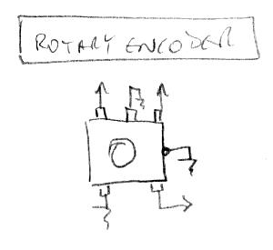
1) These are weakly pulled-up FPGA inputs for the push button switches built-in to the encoders.  Connect to either encoder pin (on the side that only has two pins) and ground the other encoder pin.

2) The banks are FPGA I/O voltage banks.  FPGAs can support all kinds of I/O standards, but if different standards are required for various things and those standards require differing I/O voltages, then they must be grouped by FPGA bank.  When you do an FPGA build / compile you get warning messages that admonish you to insure the you are indeed supplying the correct supply voltages to the banks.  The FPGA demo board bank supplies are all 3.3V (wondering when that will disappear).

You'll note that the pitch and volume axes I/O each have their own exclusive bank, and this is an attempt to electrically isolate them as much as possible from everything else going on.

Posted: 11/27/2018 2:27:01 PM
pitts8rh

From: Minnesota USA

Joined: 11/27/2015

1) These are weakly pulled-up FPGA inputs for the push button switches built-in to the encoders.  Connect to either encoder pin (on the side that only has two pins) and ground the other encoder pin.

Doh!  I already had the push buttons connected by following the separate encoder drawing that you had made, so I'm thinking Power Board? Lead plate?

Also meant to to clarify a couple things about power so I don't have to search through previous posts and emails...

1) Is the FPGA itself really the sole source of regulated 3.3v for all non-AFE requirements (no extra regulator)?  and

2)  Would your long-term plan be to power the theremin through the UART with a USB power adapter rather than a traditional wall-wart and power jack?  I'm thinking of the purely hypothetical scenario when the design is stable (ha) and there is never any need to have it connected to a computer.

Posted: 11/27/2018 3:58:34 PM
dewster

From: Northern NJ, USA

Joined: 2/17/2012

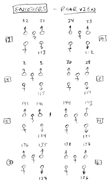
1) I was kinda wondering why you provided connectivity for every encoder pin!  Sticking both previous drawings here together for reference:


The center rotary pin is grounded, as is one of the pushbutton pins (doesn't matter which), as well as the case (ESD).  The numbers in the lower drawing are the FPGA pins they go to (though of course you have optional analog debounce RC interposing).  I've encountered encoders which use a reverse sense on the rotary pins (CW vs. CCW).

1) Yes, 3.3V is from the FPGA board.  I'm trying not to tax it as that regulator gets pretty warm, though I do use it for the LCD backlight.

2) The UART cable power wires are pretty thin, and I've had lots of power droop issues with it's USB connector, so it's not a very good short-term solution either!  My USB Blaster provides some leakage power back so I tend to keep that plugged up.  I tried using my Kindle Fire USB AC adapter rather than my PC as the 5V source but that sometimes glitched the UART so hard it locked up the processor (I have a known overflow bug in the CLI that I need to address at some point - thread 7 is a pain to debug and the CLI code is rather spaghetti-ish) and it doesn't provide an AC ground, where as my PC does.  

So the USB provides ground as well, and it may be easier to find an AC grounded USB adapter than an AC grounded wall wart?  Or go with a separate ground wire, but that seems too fiddly for most.  One could pull the SPDIF adapter into the case, run Theremin ground to the RCA barrels, and get the ground via whatever audio equipment it's connected to.

I've got so many USB AC adapters laying around, it seems like a standard that's really catching on.

Not to scare you, but when the 5V droops so low it makes the 3.3V droop, the LCD brightness flutters depending on what the FPGA is doing, kind of an inadvertent busy indicator.

Posted: 11/27/2018 5:02:04 PM
pitts8rh

From: Minnesota USA

Joined: 11/27/2015

1) I was kinda wondering why you provided connectivity for every encoder pin!

I brought everything out and added debounce filtering to the pushbuttons because whenever possible I like to add generalized connections so that boards can potentially be used elsewhere when prototypes are junked.  I like having a collection of building-block pcbs with header pins that can be interconnected for other purposes.

So the USB provides ground as well, and it may be easier to find an AC grounded USB adapter than an AC grounded wall wart?  Or go with a separate ground wire, but that seems too fiddly for most.  One could pull the SPDIF adapter into the case, run Theremin ground to the RCA barrels, and get the ground via whatever audio equipment it's connected to.

I think that last idea is the winner.  The Subscope uses a simple wall-wart and obtains its ground through the audio cable.  So if we use an external wall-wart, say 9v or so regulated to 5v and 3.3v on board, how should the UART be handled (ground connected, 5v not, or something else)?

On a side note: the main board layout that I have nearly completed is relatively large and complex as homemade boards go, and I'm starting to question whether I should first make a simpler toslink/eeprom/power distribution board like yours with jumper interconnects just to get up and running. I think there are too many uncertainties at this point to go to the effort of fabbing the larger main board (with all those hand-drilled holes) that is almost certain to change.  I am already putting too much into this prototype, and I would like to fire it up before investing too much more in what may be a wasted layout.  This should speed things up a bit.

Posted: 11/27/2018 6:09:43 PM
dewster

From: Northern NJ, USA

Joined: 2/17/2012

"I brought everything out and added debounce filtering to the pushbuttons because whenever possible I like to add generalized connections so that boards can potentially be used elsewhere when prototypes are junked.  I like having a collection of building-block pcbs with header pins that can be interconnected for other purposes."  - pitts8rh

Ah, that makes a lot of sense!

"I think that last idea is the winner.  The Subscope uses a simple wall-wart and obtains its ground through the audio cable.  So if we use an external wall-wart, say 9v or so regulated to 5v and 3.3v on board, how should the UART be handled (ground connected, 5v not, or something else)?"

All of the things that use 5V are all LDO regulated at point of use (the tuner LEDs are current regulated) so I don't think you would need to use 9V unless you think the feed v-drop will be significant.  The power issues my prototype experiences are caused by (in order from most to least significance):

1. The USB connector on the UART cable.  I can wiggle it where it connects to the USB extender cable (pretty beefy looking things from Amazon) and watch the LCD backlight flicker.  I've tried both USB2 and USB3 extender cables and the weak point is always the UART USB connector.  Tried reflowing the solder but it seems to be the connector itself that's flaky.
2. I believe my PC USB voltage is a bit low, probably due to the crazy power cycling issue my USB blaster has.  I think they use PTC's to protect against shorts, and mine has definitely been exercised that way.  The Amazon Fire USB AC adapter makes the LCD backlight brighter.
3. At one point the power toggle switch was acting up (used from my junk box) - replaced it but I still don't completely trust it.
4. I soldered the UART push-on connectors to their wires just to eliminate that as a source of v-drop, but the power wires are quite thin.  

I should cannibalize other USB stuff and make me a $6,000,000 UART cable.

I don't know how to handle the UART cable with external powering, though I suppose I wouldn't connect its +5V to the Theremin.  If there are series resistors on the board that would help with power cycle.  I'll take a look at this next time I'm trying to fix mine.

"On a side note: the main board layout that I have nearly completed is relatively large and complex as homemade boards go, and I'm starting to question whether I should first make a simpler toslink/eeprom/power distribution board like yours with jumper interconnects just to get up and running. I think there are too many uncertainties at this point to go to the effort of fabbing the larger main board (with all those hand-drilled holes) that is almost certain to change.  I am already putting too much into this prototype, and I would like to fire it up before investing too much more in what may be a wasted layout.  This should speed things up a bit."

You have much more in the way of fab experience / resources than I do, so even your "experimental" stuff is going to be a lot more "finished" than mine.  This is actually the first project I've gone out of my way to do as flexibly and skankily as possible, and wow, for a largely ergonomically-based product, it's been a real eye-opener.  Hugh Le Caine would work late into the night, soldering tubes and other components together in long strings splayed out on the workbench, and in the morning one of his tech assistants would stick it in a chassis and pretty it up, with the final real polish only if it went to market.  (I need a technician - or a clone!)

I think the next acoustic guitar I build will be a prototype with the body made of paper mache.  That's another ergonomic project that could benefit greatly from a lot of relatively painless tinkering.

Posted: 11/30/2018 7:29:27 PM
dewster

From: Northern NJ, USA

Joined: 2/17/2012

Furtherer Adventures In Pitch Correction

Been giving this a lot of thought and some experimentation.  Just about any approach that amplitude modulates the quantization function will give you some kind of pitch correction that works most of the time.  The rub is what it does to the pitch between notes.  If the quantization function has a steep slope at the note transition point and the amplitude modulation is performed via low pass filter, then if you move your hand slower than the filter cutoff you get quantization.  The same thing happens with an extreme sinus quantization function amplitude modulation via filtered absolute velocity.  Is this what we want?  If not, at least for the second case we can dial back the sinus to make it less extreme.  But the sinus imparts a lot of slope in trade for transition smoothness, so I think it is probably not the most ideal function to pick here.  I'm currently using an unsigned line segment for the volume knee which is working great, so I need try a signed line segment for the pitch correction quantization function.  The dots have to be connected somehow, and a line segment gives the least slope between adjacent note correction regions.

Posted: 12/3/2018 4:07:54 AM
dewster

From: Northern NJ, USA

Joined: 2/17/2012

So Roger, I'm looking again at the Voicelive info you kindly posted here [LINK] (manual knob descriptions) and here [LINK(your notes on it).  Not trying to pin you to the mat or anything, just picking your brain a bit.

If it behaves like they are using velocity (and I wouldn't doubt that as it's an entirely reasonable approach), then I would kind of expect a knob to control the velocity gain?

A velocity type approach seems technically inconsistent with their description of the cent window operation.  I mean, it would be velocity modulating the quantization, not leaving and entering a window?

I could see a window-centric approach working too, but I'm not sure how it would segue from correction to no correction.  I don't think it could happen instantly without hearing it.

It could be that someone non-technical wrote the manual (a fairly common occurrence) and the description of the correction mechanism got lost in translation?

I ask because I've got something working pretty good now that is much more like your observations and as opposed to the manual description.  It take 4 knobs though, and velocity gain is a fairly essential knob, which confuses me.  The quantization is line segment-based, and the knob for that controls the correction plateau or "window" width.  So I've got knobs that correspond to the knobs the manual describes, but it's velocity-based rather than window-based.

Posted: 12/3/2018 10:19:50 AM
pitts8rh

From: Minnesota USA

Joined: 11/27/2015

Until I get a chance to revisit the Voicelive's behavior with some test equipment, I really shouldn't speculate further on observations made two years ago.  I am prepping for what will be a busy week, but I will try to test out the specific area in question by this time next week.  I should be in a much better position now to see what is actually happening with pitch capture and correction.  So to paraphrase, let's table that discussion for a later date.

In the meanwhile, there is always pitch-preview that could use some loving attention...

Posted: 12/3/2018 1:45:43 PM
dewster

From: Northern NJ, USA

Joined: 2/17/2012

OK, yeah it's seasonal (and other) crazy time around here too.  If it's not obvious, I've been doing deep dives on many of the functional basics so as to nail them down for the D-Lev's Minnesota debutante ball :-).  The pitch correction is in a much better place now - it's more transparent, though also more nuanced to adjust.  I think I'll retain a version of the debug filtered velocity display on the pitch correction UI screen to aid user adjustment.

And there's one last (!) Hive opcode change I'd like to do, which is to bring back immediate AND, OR, XOR, along with a small-ish re-org of the encode/decode. (I miss the reverse subtract, but not quite enough to bring it back as well.)  Would like to do that before you get to the FPGA pump as it affects the default SW load.  Absolutely no pressure, but any even vague ETA on that, just to be ready-er for it on my end?

Posted: 12/3/2018 9:41:49 PM
pitts8rh

From: Minnesota USA

Joined: 11/27/2015

Just to take any pressure off either of us for the month, why don't we just say probably no earlier than January.  I can finish my D-Lev hardware, and if I'm waiting for anything from you at some point, I'm  certainly not going to be complaining.  I've got the Melodia, some Subscope mods, the CNC conversion project from hell, two new used machines to set up, a couple surgeries, and oh yeah, Christmas in there too.

Take your time and have some holidays!

You must be logged in to post a reply. Please log in or register for a new account.