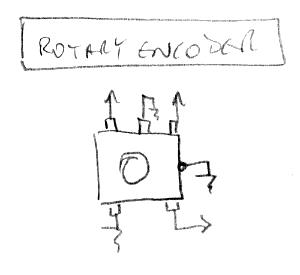
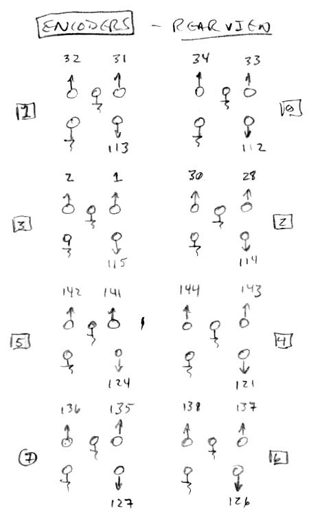
"I brought everything out and added debounce filtering to the pushbuttons because whenever possible I like to add generalized connections so that boards can potentially be used elsewhere when prototypes are junked. I like having a collection of building-block pcbs with header pins that can be interconnected for other purposes." - pitts8rh
Ah, that makes a lot of sense!
"I think that last idea is the winner. The Subscope uses a simple wall-wart and obtains its ground through the audio cable. So if we use an external wall-wart, say 9v or so regulated to 5v and 3.3v on board, how should the UART be handled (ground connected, 5v not, or something else)?"
All of the things that use 5V are all LDO regulated at point of use (the tuner LEDs are current regulated) so I don't think you would need to use 9V unless you think the feed v-drop will be significant. The power issues my prototype experiences are caused by (in order from most to least significance):
1. The USB connector on the UART cable. I can wiggle it where it connects to the USB extender cable (pretty beefy looking things from Amazon) and watch the LCD backlight flicker. I've tried both USB2 and USB3 extender cables and the weak point is always the UART USB connector. Tried reflowing the solder but it seems to be the connector itself that's flaky.
2. I believe my PC USB voltage is a bit low, probably due to the crazy power cycling issue my USB blaster has. I think they use PTC's to protect against shorts, and mine has definitely been exercised that way. The Amazon Fire USB AC adapter makes the LCD backlight brighter.
3. At one point the power toggle switch was acting up (used from my junk box) - replaced it but I still don't completely trust it.
4. I soldered the UART push-on connectors to their wires just to eliminate that as a source of v-drop, but the power wires are quite thin.
I should cannibalize other USB stuff and make me a $6,000,000 UART cable.
I don't know how to handle the UART cable with external powering, though I suppose I wouldn't connect its +5V to the Theremin. If there are series resistors on the board that would help with power cycle. I'll take a look at this next time I'm trying to fix mine.
"On a side note: the main board layout that I have nearly completed is relatively large and complex as homemade boards go, and I'm starting to question whether I should first make a simpler toslink/eeprom/power distribution board like yours with jumper interconnects just to get up and running. I think there are too many uncertainties at this point to go to the effort of fabbing the larger main board (with all those hand-drilled holes) that is almost certain to change. I am already putting too much into this prototype, and I would like to fire it up before investing too much more in what may be a wasted layout. This should speed things up a bit."
You have much more in the way of fab experience / resources than I do, so even your "experimental" stuff is going to be a lot more "finished" than mine. This is actually the first project I've gone out of my way to do as flexibly and skankily as possible, and wow, for a largely ergonomically-based product, it's been a real eye-opener. Hugh Le Caine would work late into the night, soldering tubes and other components together in long strings splayed out on the workbench, and in the morning one of his tech assistants would stick it in a chassis and pretty it up, with the final real polish only if it went to market. (I need a technician - or a clone!)
I think the next acoustic guitar I build will be a prototype with the body made of paper mache. That's another ergonomic project that could benefit greatly from a lot of relatively painless tinkering.


