Let's Design and Build a (mostly) Digital Theremin!

Posted: 7/30/2020 3:29:13 PM
dewster

From: Northern NJ, USA

Joined: 2/17/2012

"Btw., for a while now you can explicitly state types in Python, where you think it counts."  - tinkeringdude

Thanks for that!  I saw some code using types a bit ago.  I'm trying to redo my calculator with Tkinter and I've almost got a complete non-functioning (widgets with no associated calculator code) mock-up.  Many of the widgets don't resize automatically with the "sticky" parameter, which is annoying.  There's a ton of bad examples on the web too, where they make the overall winow size some fixed number of pixels, and then the buttons and such don't fit.  The way to do it is to let the window fit to the layout grid.

============

I'm using someone else's thread library function to generate plastic threads in OpenSCAD - specifically, an M25-2 for the axis antenna & coil mounts.  I made a little round nut and a hex head bolt to do thread printing tests, but I'm having to add quite a bit of clearance to the female thread (1mm!) which is making me think of writing my own thread library function, as I've probably got enough SCAD chops at this point to do it. 

Posted: 8/2/2020 3:10:52 AM
dewster

From: Northern NJ, USA

Joined: 2/17/2012

Threads

It seems many of the higher level geometric convenience functions in OpenSCAD can cause a lot of churn and other issues when applied.  One thread library uses skin() to cover a big pile of polyhedron gaps; the thread library I was using employs slight overlap to cover the gaps.  You can directly describe polyhedrons with a large number of faces (rather than make individual polyhedrons), so that is what I set out to do.  Turns out making the whole thread spiral one polyhedron causes issues too, so I limited it to a quarter turn and copied that (sigh). 

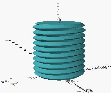
Above is 20mm of an M20 x 2 external thread with top and bottom lead-in chamfers, created with my own thread library.

And that thread library I was using doesn't really address fit tolerance, other than making internal threads a bit larger (+h/20, a linear offset based only on thread pitch, which isn't a terrible approximation, but it should be applied to shrinking external threads as well).  Looking into metric tolerance in general and doing some graphing of metric tolerance charts, log/log gives a more or less straight line, which means it's a scaled power type thing.  Square root works quite well, and applying this to the thread tables I can get a function based slightly on the square root of the diameter and more strongly on the square root of the pitch that fits the thread tables fine (within ~0.01mm).  I have yet to implement this tolerance function in my SCAD thread code, and plastic threads will require quite a bit more clearance than metal threads.

Looking around our home pantry, plastic lids tend to use a "shark fin" type thread, where the mating face is 90 degrees and the back support is something like 45 degrees, often with the tip rounded and multiple lead.  I wanted to do this for the D-Lev printed threads, but printing the 90 degree face would be problematic for the male thread.  Standard 60 degree threads seem to print OK, though they do cause compression / expansion forces when tightened.

This all takes me back to my QC / machine shop days (another lifetime), and it's quite interesting to have a better understanding of tolerance and threads.  The eternal irony is that in order to validate what someone else has done, one must acquire a deep understanding of it, but real understanding only comes from doing it yourself.

[EDIT] It seems most of the real thread sizing goes on with external (male) threads?  There are more thread grades there anyway.

Posted: 8/3/2020 10:44:27 PM
dewster

From: Northern NJ, USA

Joined: 2/17/2012

More Threads

Today while cleaning up my OpenSCAD thread file I decided to veer from the ISO Metric standard a bit.  It's one thing to cut threads in steel, it's another to print them in plastic.  There's a basic thread factor in the standard 'H' that sets all the dimensions.  Since the thread is 60 degrees, and H is the theoretical distance from the thread triangle minimum to the thread triangle maximum, this means H = P * sqrt(3) / 2, where P is the thread pitch.  The nominal diameter (e.g. 10mm for M10) + H/8 is the location of the thread triangle maximum.  The H clearance allowances for the thread ID and OD peaks in the standard are asymmetrical, and I decided to make them symmetrical.  Sizing is still based off nominal, so it isn't a huge deviation from the standard.  But the flats as seen in both male and female threads at their IDs and ODs are now all equivalent, and the OD of the male thread is a bit smaller than the standard dictates.  All flat clearances are H/8.

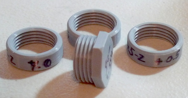
Above is a test bolt and some test nuts I printed out today with M25-2 threads.  The bolt is undersized by 0.5mm, the nuts are oversized by 0, 0.25mm, and 0.5mm.  0 is too tight, 0.25 is about right, 0.5 is pretty loose.  So combining these sizeings, it seems 0.75mm overall is a good ballpark clearance for 3D printed M25-2 plastic threads, and I would probably evenly split that between them for any real parts (~0.4mm for each at 2mm pitch).

For these clearances I'm just scaling the nominal diameter, and everything else follows from the H geometry, which seems sufficient.

Posted: 8/7/2020 11:31:21 AM
dewster

From: Northern NJ, USA

Joined: 2/17/2012

Yet More Threads

With ISO threads, the thread walls and base form an equilateral triangle with 60 degrees at each vertex.  If one employs the exact same geometry for mating male and female (!) threads, a bit of drawing / math makes it clear that the peak & valley clearance is double that of the wall clearance, so these should take care of themselves once sufficient clearance is given to the walls for proper fit at the pitch diameter.  One wants to have the threads engage with as much wall area as possible for strength reasons, but the tips aren't all that structural, so the question is how much to retain.  I decided to throw away 1/8 of the tip, and this is what the ISO standard also picks for the male thread.  Keeping clearances symmetrical means I should throw away 1/8 of the valley by filling it in, leaving 3/4 of the total wall area left.  I printed up some more test bolts and rings using this scheme, and the fit is essentially the same as the geometry scheme I was using above, so I'll go this route unless I run into trouble with it. 

The ISO standard clearances and tolerances are concerned with metal machining methods, and threads coming from disparate sources fitting together correctly.  Whereas, when you are printing both parts on the same printer you are in control of everything, and a completely symmetrical geometry can work.

The ISO standard picks the male triangle -1/8 the tip as the nominal diameter (e.g. ~10mm for an M10 thread) which I assume is to make standard bar stock work out.  It also makes it trivial to measure and then know the nominal thread.  If I were to make a "plastic thread" standard from scratch I'd probably pick a bit more shaved off the tip as nominal, as -1/8 is rather pointy.  Doing so would enlarge the pitch diameter a bit, which is why I've decided against this (I don't want to deviate too far from the ISO standard).

[EDIT] Here's a link to my OpenSCAD thread files: [ZIP].

=================

Updating my D-Lev mission critical PC from Linux Mint v19.3 = v20 caused my terminal-based calculator, Hive simulator / assembler, and D-Lev librarian to break.  I tracked it down to getchar() not working when the terminal was placed in "raw" (non-canonical, no echo, VMIN & VTIME=0) polled mode.  Modified the code to use to read() instead of getchar() and now everything seems to be working OK again.  Weird.

Posted: 8/10/2020 6:19:08 PM
dewster

From: Northern NJ, USA

Joined: 2/17/2012

Yet Even More Threads (Too)

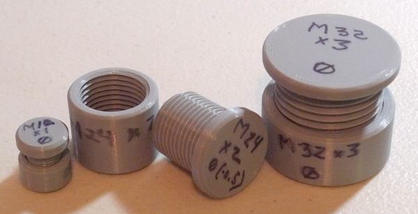
I printed out a range of thread sizes to test clearance based on the thread pitch, which the ISO standard seems to do.  The formula I came up with was a diameter adder proportional to the square root of the thread pitch, to wit: sqrt(P) / 3.  For an M12x1 (where P=1) this gives a clearance of +/-0.333 to both male and female threads, which was too tight.  I found that adding 0.25 to the female thread gave it a really nice (not too loose, not too tight - goldilocks) fit.  The M24x2 (P=2) was just about right with no adjustment.  The M36x3 (P=3) felt somewhat too loose (and is mislabeled below, Trump Sharpie syndrome):

Thinking about this, the good M12x1 has 0.916mm total diameter clearance, the good M24x2 has 0.94mm, and the loose M36x3 has 1.15mm.  It seems the thread clearance, over this range at least, should be constant, so I set it to 0.5 for each (+0.5 for female, -0.5 for male) which gives 1mm total diameter difference.  Which seems like a lot, but radially it's half this or 0.5mm, and for each 60 degree face it's half that or 0.25mm, which seems reasonable.  It's actually pretty amazing that you can 3D print to these kinds of tolerances, and with any consistency (particularly the tiny M12x1 threads).  Anyway, now I can move on to designing and printing out some antenna / coil mounts.

Posted: 8/10/2020 8:44:55 PM
dewster

From: Northern NJ, USA

Joined: 2/17/2012

Quartus (Intel / Altera FPGA Tool)

The upgrade process from Linux Mint 19.3 to 20 caused the FPGA tool I've been using (Quartus 19) to have even more GUI icons and entry fields go missing.  So I went to the Intel web pages to see if anything new had been released, and indeed v20.1 was available - but the link was broken!  After an hour or more of seeing how others were dealing with this (a common occurrence, it seems), someone in the fora gave direct links, and it seems you can manually manipulate the URL via pattern recognition:

  http://download.altera.com/akdlm/software/acdsinst/20.1std/711/ib_tar/Quartus-lite-20.1.0.711-linux.tar

Then you just untar the file and run the included install script.  Voila, all GUI widgets functioning!  But the Byteblaster was again non-functional. :-( 

Running this: /home/demo/intelFPGA_lite/20.1/quartus/bin/jtagconfig I got:
   1) USB-Blaster variant [5-1]
   Unable to lock chain - Insufficient port permissions

So I added this file: /etc/udev/rules.d/51-altera-usb-blaster.rules with the following contents then rebooted:
    SUBSYSTEM=="usb", ATTR{idVendor}=="09fb", ATTR{idProduct}=="6001", MODE="0666"
    SUBSYSTEM=="usb", ATTR{idVendor}=="09fb", ATTR{idProduct}=="6002", MODE="0666"
    SUBSYSTEM=="usb", ATTR{idVendor}=="09fb", ATTR{idProduct}=="6003", MODE="0666"
    SUBSYSTEM=="usb", ATTR{idVendor}=="09fb", ATTR{idProduct}=="6010", MODE="0666"
    SUBSYSTEM=="usb", ATTR{idVendor}=="09fb", ATTR{idProduct}=="6810", MODE="0666"

But before I program I have to open a terminal and run this:
    sudo killall -9 jtagd
    sudo killall -9 jtagd
    /home/demo/intelFPGA_lite/20.1/quartus/bin/jtagd --foreground --debug

That fixes the genuine Byteblaster, but I still can't get my cheezer fake one to complete a programming cycle.

On a side note, the GUI widgets in WPS Office were messing up too, so I uninstalled it and went with the Flatpak version in the SW manager, and that's working like a champ.  Had to get out my MS fonts files and install them, now it's not complaining about them missing.

The Cura slicer SW was alarmingly missing menus and had blank panels, and someone recommended this fix, which worked for me:
    rm -rf ~/.cache/qtshadercache/*

I'm happy these measures improved things, but it sure was a painful couple of days.

Posted: 8/14/2020 7:07:26 PM
dewster

From: Northern NJ, USA

Joined: 2/17/2012

The Good, the Bad, and the Ugly

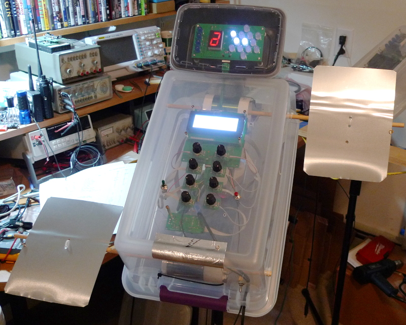
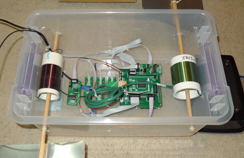
Tired of all the trouble that the flaky DuPont connections are causing in my first prototype, yesterday I finally got around to putting the AFE's and some coils into my second prototype, which consists of Roger's beautiful PWBs supported by various household items, the totality of which is ensconced in my messy lab area:

The antennas are scrap aluminum flashing zip-tied to 18" lengths of 5/16" wooden doweling and electrically connected via thin bus wire & springs - this is only a test!  Here's the inside:

I've got the pitch side AFE (on the right) mounted on a single brass threaded spacer off of the the main PCB, the volume side AFE (on the left) is on an identical spacer off of the plastic cabinet (the hole was already there).  The coils are just zip tied in, and zip-ties also keep the ends of the dowels from falling inside.  Some 26AWG bus wire connects the antenna plates to the AFEs, I wanted to use wussy wire here to minimize weird C fields and such (the plates s/b where the action is at).  The pitch coil is ~4mH, the volume ~8mH, and these were just what I had laying around.

It's not hard to play, though of course it doesn't feel quite as comfortable as the first prototype which I've been playing for a couple of years now (eek!) and time will tell if I fully acclimate to it.  A bit surprisingly, the plates are far enough apart that my playing motions don't cross-pollinate.  Acal seems twitchier, and I'm not exactly clear as to why that might be.  The far-field null seems to drift around a bit more.  I never have to adjust Pcal on the first prototype, whereas I have to often trim it on this one - part of this is the twitchy acal, which I heavily rely on to do the trimming for me.

From an engineering standpoint it's really hard to beat having the coils mounted directly behind large plates, and having these mounted away from the main control box.  But coils inside the main box are much easier from a manufacturing standpoint, and you don't have to deal with external cabling either.

Whence the title of this post, I found myself accidentally playing it when setting up the linearity of the new prototype with the human whistle preset that I just happened to be using at the time (I added some external reverb): [MP3].  5 half steps are used in it a lot, which is just over my open/closed hand sensitivity preference.  Key of C#?  RIP Ennio Morricone.

Posted: 8/16/2020 6:45:09 PM
dewster

From: Northern NJ, USA

Joined: 2/17/2012

Planesong

[MP3]

Posted: 8/16/2020 8:56:47 PM
pitts8rh

From: Minnesota USA

Joined: 11/27/2015


Posted: 8/16/2020 2:18:50 PM by oldtemecula:

It seems digital DSP sound can only poorly imitate the sounds of nature which really impresses you. We all have our own taste.
Christopher
Edit: I will delete this at some point, do not want to be associated with your approach.


Too late, you should have deleted yourself earlier.  Much earlier.

Posted: 8/17/2020 1:27:48 AM
dewster

From: Northern NJ, USA

Joined: 2/17/2012

"... I have family that lives near you, this should be no surprise.  I like that little redwood front porch."  - oldtemecula

Yeah, it would be a shame if something happened to it.

TW mods:  Is this acceptable behavior?  "Watch out, I know where you live?"  How bad does this have to get before you act?

"... the way I see it you got just over 4 months left."

Lordy, it's like dealing with the mob.

You must be logged in to post a reply. Please log in or register for a new account.