Everybody Do The Twist! (Encoder Conditioning Redux)
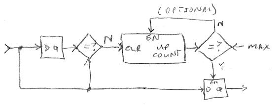
I've re-architected ALL of the input sampling and conditioning. The encoder pushbuttons and GPIO inputs are stability debounced en masse which is ultra efficient in terms of code and real-time. Here's how it works:

A vector of encoder push buttons / GPIO are presented to the input, and compared to the past input. If new and old are not equal then the counter is reset. If they are equal then the counter counts up. When the counter hits the maximum the input is registered to the output. If you think about it stopping the counter at max isn't necessary, but leaving that out makes it rather tricky. This construct ensures that all inputs are stable for a period of time before they are sent on to the rest of the software, and the time period I picked is 25ms - you want the longest time here that you won't notice as a delay. Obviously one flailing input could kill all the others, so we're assuming things are generally all quiet on the western front, luckily that seems to be the case.
For the rotational data from the encoders, I designed a highly similar stability construct which operates on the sampled clear-on-read register data. A fast twist gives about 16 detents in about 0.1sec, so say 200Hz. 1/200Hz = 5ms, and in practice I found that a timer value of 3.3ms works well. It's vitally important to enforce a minimum detent time if you are implementing a velocity speed-up, because glitches from a noisy encoder will be interpreted as fast spins, adding injury to insult.
On my third prototype the two lower two encoders which surely have the most wear (selecting voice and tooling around the UI) are kinda jumpy and do somewhat large reverses now and then. I notice that after some "exercising" they get better, so it's clearly a contact wear issue at work here. On one hand you want velocity so you don't prematurely wear out your encoders, literally spinning them to death, on the other hand velocity will bring out the worst in a worn encoder (rock & hard place). It's been bothering me that so much basic conditioning, and worse quadrature decoding, is going on in the HW which ties my SW hands in terms of patching things up. But I've come to feel this isn't quite so non-ideal.
In the FPGA hardware the encoders lines are individually linearly filtered with 2^14 width accumulators clocked at 180MHz. The hysteresis width is 1/3 the width, so the minimum time the sneakiest glitch could sneak through is: 2^14 * 1/3 * 1/180MHz = 30us, or 33kHz. Since a fast twist gives a detent rate of around 200Hz, and we need to sample and detect the quadrature events for each detent - say 4 times this absolute bare minimum or 800Hz. 33kHz / 800Hz = 41.25 or about 2^5 or 5 bits margin. I upped the accumulator width to 16 but didn't notice the flaky encoders improve much, if at all. But you can't be too careful with glitchy data coming from the outside world so I'm going to leave it at 16. With this the FPGA logic utilization is 90%.
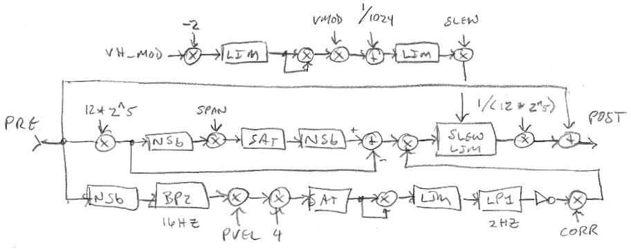
After trying several different approaches to rotational velocity sensing I settled on a linear decay:

The sampled and stability debounced encoder data is presented to the input. This is -1, 0, or +1 scaled up to 1/4th the width of the accumulator register. If the input is non-zero it is added to the register, saturated (not shown), and registered. Otherwise a fixed increment is added or subtracted from the registered value in order to drive it in the direction of zero. For those instances where the increment value is too large and would result in overshooting zero the register is cleared to zero, and this is necessary in order to prevent oscillation. Note that the output is the old accumulated value before the current input is added. Most of the time the input will be zero, but when input pulses of the same sign come in close enough together the previous one will not have decayed to zero, so the new one will add to the accumulator. Enough quick pulses will add up in the accumulator and saturate it, giving us a 4x velocity gain maximum. Using signed accumulation here will tend to "knock down" the sum if the values that are coming in quickly are of different polarity and reduce the velocity value for that impossible (in a perfect world full of perfect encoders) and therefore error condition. The absolute value of the velocity is taken, and 1/2 is added to this before it is quantized which is necessary in order to center up the velocity action. Finally this is multiplied by the encoder -1, 0, +1 value in order to restore the sign and gate it, then it and the encoder value is added to a running total.
Another error condition I finally realized and dealt with is the ambiguity of the encoder rotation value -2 in the FPGA register. When the hardware detects a clockwise detent it increments a two bit counter; counterclockwise detents decrement the counter. A glitch can easily result in a count of two or more change between sampling times (which clears the counter). Since the counter is modulo, two clockwise or counterclockwise counts will give the same result of -2, so I've added code to kill that whenever it is encountered by the software.
The above actions take place at the audio interrupt rate of 48kHz, which is firmly in overkill territory in terms of the required sampling rates. In order to save real time I'm using a three bit counter to schedule the rotational processing of the 8 encoders one at a time, and do all sampling and debouncing only with encoder[0]. So the sampling and processing rate is 48kHz / 8 = 6kHz.
You haven't had your HW & SW ass properly kicked until you meet up with a gang of encoders in a dark alley. 
[EDIT] Forgot to mention: The GPIO and encoder input information is massaged as described above via the thread 7 interrupt service routine. The otherwise continuous code in thread 7 is an infinite loop dealing with 1) the serial port command line interface which is used to interact with this human and the librarian software, and 2) the D-Lev user interface, which must process the input information further, scale the encoders for direct use by the software, update the LCD, etc. How do you get the encoder rotation data from the ISR domain to the main thread? What make this complicated is the unknown timing between the domains (if you know one is faster then you can rely on Nyquist guarantees). The trick is to have no handshaking, just condition the data and store it, then let the other side read it and further condition it / detect changes as necessary. Accumulate rotations and have the other side differentiate it, and as long as the modulo time isn't exceeded no data will be lost. Rather like FIFO pointer exchange, it's likely a problem with only one simple solution. In all things, whenever possible, feed-forward is the thing to pick, feedback the thing to avoid.


