Scanning With DC
One of the central jobs when designing a digital Theremin is the mitigation of internal interference of the digital switching variety. Several approaches are employed on the D-Lev, and the most basic is to not generate it in the first place (e.g. the LCD isn't updated unless needed).
Currently the encoders consume 3 FPGA pins each, for a total of 8 * 3 = 24 pins -- which is a lot of pins! Each pin is debounced in FPGA hardware via linear hysteresis, but they are dealt with one at a time in software, and users generally are only spinning one at a time, so all the parallelism and electrical energy consumed largely go to waste. And all those wires are a pain in the ass to solder! Might there be a better way?
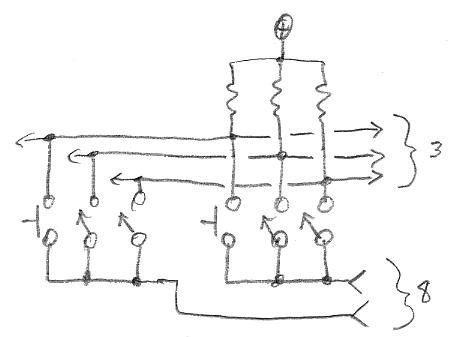
The above is what I intend to try soon. Each of the three contacts on all of the encoders would be wired in parallel and given a single FPGA pin and a pull-up to +3.3V (3 sense pins total). And on the other side, all contacts of each encoder would be wired together and driven by an FPGA pin (8 encoders so 8 drive pins total). So 3 + 8 = 11 pins for 8 encoders, plus maybe 1 wire for ESD bleed, so we've cut the wire count in half! My soldering iron breathes a sigh of relief...
On the switching side of things:
1. All 8 drive pins would be held at ground until some high=>low activity is seen on any of the sense pins.
2. A three level binary search of the encoder drive pins would then determine which encoder is active:
Let's suppose encoder [7] is active:
a. Lift [0:3] => no change, so the encoder is [4:7].
b. Lift [4:5] => no change, so the encoder is [6:7].
c. Lift [6] => no change, so the encoder is [7].
d. Ground [7] (already done in this case), debounce, decode button press / encoder rotation.
I think it's important here to not use analog debouncing, so the active encoder can be detected and decoded as quickly as possible. And the active encoder should be kept under active surveillance for a short period of time after it has gone inactive to properly track fast rotations and minimize bounce.
One could possibly use bipolar drive rather than open drain to speed things up, but that could produce drive contention if two encoders are twisted at once. Perhaps a small current limiting resistor in series with the drive would work though, and could help limit ESD current back to the FPGA too.
Anyway, I like this approach because it is more SW oriented, so any trouble with noisy encoders could be addressed with SW updates, rather than FPGA pumps.
[EDIT] For step d.) above, one could actually ground all of the encoders (not just [7]) and use the short timeout to decide whether or not to do the binary search on new activity.