Let's Design and Build a (mostly) Digital Theremin!

Posted: 10/15/2022 2:40:53 PM
Mr_Dham

From: Occitanie

Joined: 3/4/2012


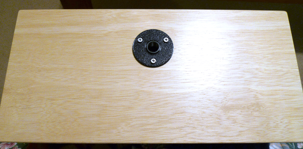
"I like the boom approach because it makes screwing and unscrewing the Theremin easier, but the downside is there is possible rotation about the boom axis." Dewster


You can probably reduce the risk of rotation by placing the mounting nut slightly higher than the center of gravity of the theremin cabinet.

Posted: 10/15/2022 2:57:50 PM
dewster

From: Northern NJ, USA

Joined: 2/17/2012

"You can probably reduce the risk of rotation by placing the mounting nut slightly higher than the center of gravity of the theremin cabinet. "  - Mr_Dham

Yes!  That's exactly what I did with the D-Lev Tour:

Posted: 10/15/2022 3:26:02 PM
dewster

From: Northern NJ, USA

Joined: 2/17/2012

Scanning With DC

One of the central jobs when designing a digital Theremin is the mitigation of internal interference of the digital switching variety.  Several approaches are employed on the D-Lev, and the most basic is to not generate it in the first place (e.g. the LCD isn't updated unless needed).

Currently the encoders consume 3 FPGA pins each, for a total of 8 * 3 = 24 pins -- which is a lot of pins!  Each pin is debounced in FPGA hardware via linear hysteresis, but they are dealt with one at a time in software, and users generally are only spinning one at a time, so all the parallelism and electrical energy consumed largely go to waste.  And all those wires are a pain in the ass to solder!  Might there be a better way?
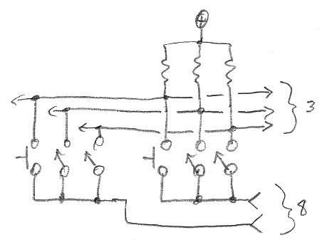

The above is what I intend to try soon.  Each of the three contacts on all of the encoders would be wired in parallel and given a single FPGA pin and a pull-up to +3.3V (3 sense pins total).  And on the other side, all contacts of each encoder would be wired together and driven by an FPGA pin (8 encoders so 8 drive pins total).  So 3 + 8 = 11 pins for 8 encoders, plus maybe 1 wire for ESD bleed, so we've cut the wire count in half!  My soldering iron breathes a sigh of relief...

On the switching side of things:
1. All 8 drive pins would be held at ground until some high=>low activity is seen on any of the sense pins.
2. A three level binary search of the encoder drive pins would then determine which encoder is active:

Let's suppose encoder [7] is active:
a. Lift [0:3] => no change, so the encoder is [4:7].
b. Lift [4:5] => no change, so the encoder is [6:7].
c. Lift [6] => no change, so the encoder is [7].
d. Ground [7] (already done in this case), debounce, decode button press / encoder rotation.

I think it's important here to not use analog debouncing, so the active encoder can be detected and decoded as quickly as possible.  And the active encoder should be kept under active surveillance for a short period of time after it has gone inactive to properly track fast rotations and minimize bounce.

One could possibly use bipolar drive rather than open drain to speed things up, but that could produce drive contention if two encoders are twisted at once.  Perhaps a small current limiting resistor in series with the drive would work though, and could help limit ESD current back to the FPGA too.

Anyway, I like this approach because it is more SW oriented, so any trouble with noisy encoders could be addressed with SW updates, rather than FPGA pumps.

[EDIT] For step d.) above, one could actually ground all of the encoders (not just [7]) and use the short timeout to decide whether or not to do the binary search on new activity.

Posted: 10/18/2022 12:33:56 PM
dewster

From: Northern NJ, USA

Joined: 2/17/2012

Radioactive

A new useless preset that mimics a Geiger counter: https://d-lev.com/audio/2022-10-18_radioactive.mp3

It uses the triple oscillator running subsonic and with some 1_OSC:sprd to randomize things. It's weird that you can clearly hear the rhythm of two offset oscillators, but add a third and it sounds nearly random. Many of the old relaxation surf / wind synth boxes employed this method.

And what day isn't complete without a tenor falling into the abyss: https://d-lev.com/audio/2022-10-18_falling.mp3

Posted: 10/19/2022 7:44:52 PM
dewster

From: Northern NJ, USA

Joined: 2/17/2012

Up Periscope!

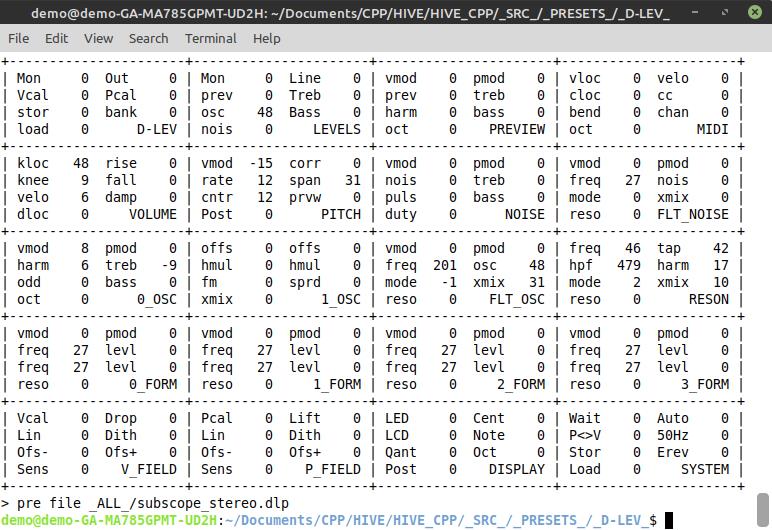
Katica kindly provided us with some audio samples from her Subscope - she likes the timbre quite a bit!  I analyzed them in Audacity and Sonic Visualizer, and it turns out the D-Lev synth is well suited to this type of voice, with very little massaging necessary beyond the basic oscillator harmonics:

It's a very mellow tone with no odd / all harmonic imbalances, so a bit of 0_OSC:harm got it ~90% of the way there.  I could see and hear increased harmonics with volume, which I introduced with some 0_OSC:vmod.  Rolling off the bass at 200Hz with a 2nd order high-pass filter, and rolling the high end off with a bit of treble reduction completed it.  You can listen to comparisons of individual E notes here, the subscope is first, followed by the D-Lev: https://d-lev.com/audio/subscope_oct_cmp_2022-10-19.mp3

The sound is quite pretty like a flute, particularly when played non-gliss: https://d-lev.com/audio/2022-10-19_he_shall_sub_his_scope.mp3

I made both stereo and mono versions of this preset - I almost always prefer stereo, but the Subscope is a mono instrument, and players of the real deal may feel more comfortable with mono: https://d-lev.com/support.html

Posted: 10/20/2022 1:52:07 PM
DOMINIK

From: germany, kiel

Joined: 5/10/2007

Nice. Of course nothing compares to the real thing :-) Strong would be if it could learn any waveform with a flip or three of the switch.

Posted: 10/20/2022 1:59:21 PM
dewster

From: Northern NJ, USA

Joined: 2/17/2012

"Nice. Of course nothing compares to the real thing :-)"  - DOMINIK

Glad you approve Dominik!  Your Subscope has a sweet tone and nice dynamics!  I believe dynamic timbre is essential for any musical instrument to have.

"Strong would be if it could learn any waveform with a flip or three of the switch."

I wish that were a simple thing to do, even off-line, and particularly for human vocals which are really tough to match to a specific vocal tract.  Still, one can learn a lot about synthesis via laborious manual analysis.

Posted: 10/20/2022 4:44:41 PM
Buggins

From: Porto, Portugal

Joined: 3/16/2017


The above is what I intend to try soon.  Each of the three contacts on all of the encoders would be wired in parallel and given a single FPGA pin and a pull-up to +3.3V (3 sense pins total).  And on the other side, all contacts of each encoder would be wired together and driven by an FPGA pin (8 encoders so 8 drive pins total).  So 3 + 8 = 11 pins for 8 encoders, plus maybe 1 wire for ESD bleed, so we've cut the wire count in half!  My soldering iron breathes a sigh of relief...

On the switching side of things:
1. All 8 drive pins would be held at ground until some high=>low activity is seen on any of the sense pins.
2. A three level binary search of the encoder drive pins would then determine which encoder is active:

Let's suppose encoder [7] is active:
a. Lift [0:3] => no change, so the encoder is [4:7].
b. Lift [4:5] => no change, so the encoder is [6:7].
c. Lift [6] => no change, so the encoder is [7].
d. Ground [7] (already done in this case), debounce, decode button press / encoder rotation.

I think it's important here to not use analog debouncing, so the active encoder can be detected and decoded as quickly as possible.  And the active encoder should be kept under active surveillance for a short period of time after it has gone inactive to properly track fast rotations and minimize bounce.

One could possibly use bipolar drive rather than open drain to speed things up, but that could produce drive contention if two encoders are twisted at once.  Perhaps a small current limiting resistor in series with the drive would work though, and could help limit ESD current back to the FPGA too.

Anyway, I like this approach because it is more SW oriented, so any trouble with noisy encoders could be addressed with SW updates, rather than FPGA pumps.

[EDIT] For step d.) above, one could actually ground all of the encoders (not just [7]) and use the short timeout to decide whether or not to do the binary search on new activity.
As for me, it looks like diodes are missing in this schematic...

Regarding noise from switching... 
I had an idea how to reduce number of pins needed to connect a lot of pots and pushbuttons.
Let's use chain of shift registers with parallel load and serial input/output.
Only three pins of FPGA are needed to connect any number of encoders.
Parallel inputs of shift registers are connected to encoders and buttons.
Pin LOAD when active will latch current state of switches (take a snapshot).
Pin SHIFT will clock shifting bit by bit captured snapshot of switch states - each clock cycle shifts one bit out of shift registers chain (e.g. ENC1A, ENC1B, ENC1C, ENC2A, ENC2B, ENC2C, ...)
Pin DATA is to read shifted out bit value.
So, to get states of N encoders with pushbuttons once, you have to activate LOAD signal for short time, then clock SHIFT signal N*3 times reading of new bit each cycle.
It should work, would not it increase noise?

Posted: 10/20/2022 5:03:30 PM
dewster

From: Northern NJ, USA

Joined: 2/17/2012

"As for me, it looks like diodes are missing in this schematic..."  - Buggins

If only one switch out of the 8x3=24 is closed, you can manipulate the bottom 8 open drain/collector leads to find out which one it is, and then use an inactivity timer to know when to do another search.  So turning an encoder quickly would retain the focus on it (with velocity calcs and such), turning it very slowly might trigger a search at each detent (where you don't care about velocity), and with no activity there would be no active searching going on to cause noise.

"Let's use chain of shift registers with parallel load and serial input/output."

In the current supply chain crisis, sourcing the tuner shift register ICs was a major concern, and I ended up overbuying.  And I don't particularly like them in the first place, not enough drive control, weird internal register access, etc.  Just saying that minor parts like jellybean logic can hold up everything, but I guess you're aware of that.

"It should work, would not it increase noise?"

Since you're not multiplexing the other side of the switches, probably not.  You could always sample the switches synchronously with your sampling of the field numbers, which would put a zero there - 48kHz sampling is a nice rate!

Posted: 10/22/2022 7:57:09 PM
dewster

From: Northern NJ, USA

Joined: 2/17/2012

Hive Soft Processor Design Document Update

For the techno-curious, I finally got around to updating the design document for my Hive processor: https://d-lev.com/support/Hive_Design_2022-10-21.pdf

Tons 'o stuff changed since the last update.  For better focus, I removed the simulation section and the sample code - I could write a book on those alone.

Hive is the beating heart of D-Lev!

You must be logged in to post a reply. Please log in or register for a new account.