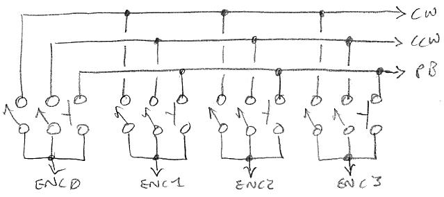
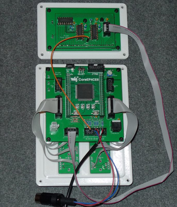
"1) Is there a wiring plan to parts that are meant to be mounted in the housing and connected to main board connector J10 (or other connectors)? Or maybe even a breakout board that accomodates all the external connectors? Very likely there is no common scheme as different people have various housings and different needs for external connectors." - gerbold
The J10 expansion port use is sort of on a case by case basis. I wire up a ribbon cable to plug into it, and then solder the other ends to whatever connectors and switches are mounted on the I/O panel. Here's a video of one version: https://www.youtube.com/watch?v=9Cs0PlpKx68
"2) Are the builtin Toslink and the serial interface all that is required to get started? The serial lines Rx and Tx are used to connect the command line librarian to d-lev, right?"
Yes.
"3) All mounting holes have a diameter of 3.2mm for M3. Just the mounting hole H5 of the d-lev_8mm_tuner has a diameter of 2.5 mm. Is the 2.5mm hole intended for cutting an M3 thread?"
Yes, tapping that hole works well.
"4) All 0.1µF ceramic C have 2.5mm pin distance. Not so C2 of the main baord which has 5mm. Does this C have to be electrically different compared to the others?"
You have a very sharp eye! I would suggest you make C2 4.7uF (polarized tantalum as is used on the AFE boards - watch the polarity!) so that the LCD backlight operates in linear rather than switched mode. This fixed an issue with internal interference that one user experienced.
"5) There are many one pin connectors of the type Con_01x01_Male. I assume the majority of these does not need to be assambled. Probabyl these are kind of test points or for future use. d-lev_main: J12 (GND), J13 (+5V), J14 (+3.3V), J20 (gpio_i[2]), J21 (gpio_i[3]), J22 (gpio_o[2]), J23 (gpio_i[3]), J24 (mido_tx_o); mido_tx_o may be the inverted midi_tx_n_o; d-lev_tuner_driver: J3 (DP); d-lev_afe: J4 (GND), TP7 (C_DIV)."
Yes, no need to populate those. [EDIT] Though TP7 (C_DIV) might come in handy for checking the divider voltage swing with a scope.
These two are probably required to connect the solenoid. But how exactly are the connections between antenna, solenoid, and d-lev_afe? d-lev_afe: J2 (L_IN), J3 (L_OUT)"
The one labeled "Drive" connects to the "cold" or low impedance end of the solenoid. The one labeled "Sense" connects to the "hot" or high impedance end of the solenoid and the antenna.
"Not clear about the ESD pin. The ESD plane is connected to the mounting solder pins of the EC11. As the mucisian touches these buttons, there is the risk of electrostatic discharge. What is to be done with these three pins? d-lev_encoders: J8 (GND), J9 (ESD), J10 (GND)"
[EDIT] I just jumper the ESD hole to the GND hole. To minimize ESD at the encoders I recommend all plastic knobs (I 3D print them) without set screws.
"6) The LCD type is not well specified..."
I agree, though probably any one you pick that genuinely takes 3.3V (i.e. has a charge pump IC) should work. 5V parts will work too, but like you say they would need jumpers. I don't have direct experience here, but Evan Khan does. The backlight is always powered via 5V to keep the load off the FPGA regulators, and this is done in a constant-current type way.
You will want to snip the contrast pot connection going to 3.3V though, that needs updating on the schematic.
"7) What are the properties of the power supply? 5V but how much A? Would a USB charger be good enough or does one need a low noise power supply? Recommendations?"
Any decent quality USB charger should do. It needs 5V at somewhere around 0.5A.
"8) The closest I can get to 38.1mm is PVC pipe with 40mm. Assuming 1mH and 2mH, these commands should calculate the solenoid, right?"
That should do it. The values don't have to be spot-on, though purchasing an LC meter never hurts in this biz.
"9) It would be quite helpfull to have some pictures:"
I'll see what I can do, but all of the built-up boards I have here are already mounted to their 3D printed panels and boxes and such. There isn't really all that much going on with the support circuitry, it's fairly non-critical, though there are things to watch out for when mounting the coils and AFE boards.


 is discussed in [1676]
 [3036] refers to a circuit proposed by Bourns for PEC11R series


 step 1: encoders
 step 2: LCD
 step 3: main board


