Theremin Circuits Scratchpad

Posted: 4/21/2013 6:53:04 PM
Juan

From: Valencia, Spain

Joined: 4/21/2013

While I was writing there has been a lot of activity. I do not write in english so fast!

The debate between tubes/transistors and old technology/modern is quite habitual in HIFI and guitar amplifier worlds. I have built some tube amplifiers (HIFI and quitar) and solid state ones and I have an opinion. The real thing is that free running tubes sound "well" when overdriven. Tubes sound no so well when overdriven if there is high negative feed back. In general all solid state amplifiers sound bad when overdriven because negative feedback must be very high in a transistor amplifier. When the system is not overdriven, well designed amplifiers sound all well (either tube or transistor).

Fred, I think that Thermen oscillator driving hard the tube is not causing nice distortions. Output are in all cases very good sinus. But the mixer tetrode is driven well in cut-off. In fact I think that if the input is not a very good sinus it does not matter, because the mixer tetrode is driven so far out of the linear region. I agree with you, and more in the case of the RCA and C Rockmore Theremins, that the tone is primarily produced in the mixer. I would bet that if an original 24 or UY-224 tetrode mixer is driven by a "modern" solid state oscillator (of correct amplitude) there would not be any difference. The sound of these glorious theremins is originated in the mixer, and modified by the ancient circuitry in the audio frequency range (modding tone, adding capacitor, etc. There are a photographs of Lev playing Theremins with levers that changed tone adding capacitors and inductors. See also Luice Rosen schematic, with lots of post mixer audio modifiers).

Posted: 4/21/2013 7:09:13 PM
FredM

From: Eastleigh, Hampshire, U.K. ................................... Fred Mundell. ................................... Electronics Engineer. (Primarily Analogue) .. CV Synths 1974-1980 .. Theremin developer 2007 to present .. soon to be Developing / Trading as WaveCrafter.com . ...................................

Joined: 12/7/2007

"I gotta disagree...theremins  using  synth-style wave shaping always sound like synths." - Chobbs

Oh, I agree that they do! ;-) ... But I dont agree that they MUST! 

The reason why I think they "do" is because the processing occurs at the audio frequencies - The frequerncy dependencies are essentially operating in the usual synth way..

Generate the frequency dependencies at the mixer (or sub-sampling engine) and one overcomes the charactaristioc subtractive synthesis 'signature'[.

At the end of the day - take any theremin waveforms and compare them, harmonic by harmonic, to any other waveform however generated.. If the waveform from your 'generator' is identical to the waveform from a given Lev theremin, then you have a 'clone' of that theremin.

And thats it really! ;-) You CANNOT do this by taking a audio waveform and processing it (or at least you cannot without taking that audio waveform and entirely reprocessing it - probably with a DSP - with all the complexities and probable latencies this incurrs) - You can only do this by creating the "clone" waveform.. Ways you can create this waveform are through additive synthesis which adjust each harmonic in a frequency and volume dependent manner, or through other sampling based methods..

But the EW simply takes a crudely generated difference frequency and distorts this, and the EW-Pro takes an audio frequency fixed shape wave and distorts this.. You cannot create the complexities of a Lev theremin waveform with such simple manipulations on the audio waveform.

my " Produce the same audio waveform as the RCA for the same physical actions, and you have a true "RCA Clone" regardless whether the audio is produced by two chickens being heterodyned or by a FPGA." was a bit sarky, but in essence I believe its true -

its the "Produce the same audio waveform .... and you have a true "xxx Clone"" which is salient - It may be difficult or impossible to do this by heterodyning two chickens, just as it may be difficult or impossible to do this with a subtractive synthesis engine! - but you CAN do this with other technologies... The only remaining question for me is, is it worth doing - is the theremin really worthy of the effort, and would enough people be interested in buying such an instrument to justify the work.. ? .. I am inclined to think the answer is no - that most people couldnt care less whether it sounds like a Lev theremin or like a EW.

And I think the above is true even for most who are "into" theremins, let alone the music listening / buying public - most of them cant tell the difference between a MiniMoog with loads of portamento and a theremin, let alone between a RCA,EW or EW-Pro or a Gakken.

Fred.

Posted: 4/21/2013 7:47:40 PM
FredM

From: Eastleigh, Hampshire, U.K. ................................... Fred Mundell. ................................... Electronics Engineer. (Primarily Analogue) .. CV Synths 1974-1980 .. Theremin developer 2007 to present .. soon to be Developing / Trading as WaveCrafter.com . ...................................

Joined: 12/7/2007

"I would bet that if an original 24 or UY-224 tetrode mixer is driven by a "modern" solid state oscillator (of correct amplitude) there would not be any difference." - Juan

I agree.

So, IMO, the real challenge is to duplicate the mixer function and post-mixer tone modifications using available solid state stuff.. This should be "all" thats needed to make a Lev "clone" - Provided one gets the front-end / linearity right.

Fred.

Posted: 4/21/2013 9:21:57 PM
Juan

From: Valencia, Spain

Joined: 4/21/2013

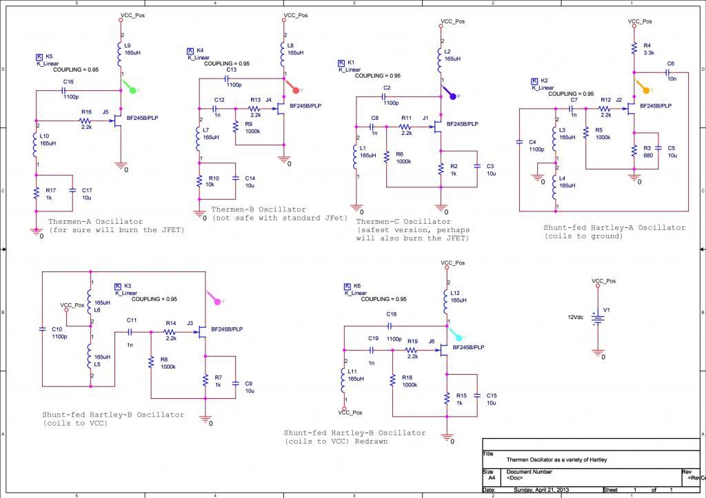
I am posting JFET versions of the various types of Hartley oscillators, including the new "Thermen" Hartley oscillator

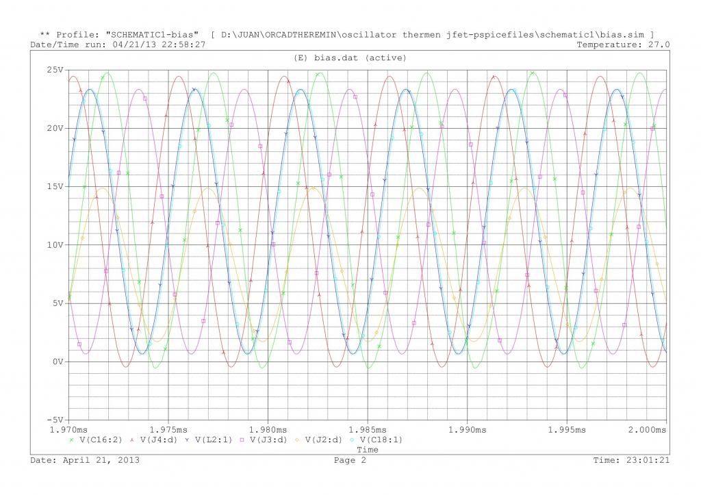
Again, I have made a direct adaptation of original tube, and then trying to make it safer. Clearly the Therman-A will burn the JFET, because initial intensity transient will be high, not to say voltage transients. A tube can withstand happily voltage peaks and (less happily) intensity transients. But a solid state device is much faster committing suicide. Perhaps Thermen-C could work.

In any case, it is quite evident that Thermen-C is equivalent to Hartley-B (more in the redrawn version). All versions produce nice sine signals, with great purity.


Posted: 4/21/2013 9:36:40 PM
FredM

From: Eastleigh, Hampshire, U.K. ................................... Fred Mundell. ................................... Electronics Engineer. (Primarily Analogue) .. CV Synths 1974-1980 .. Theremin developer 2007 to present .. soon to be Developing / Trading as WaveCrafter.com . ...................................

Joined: 12/7/2007

You certainly know your oscillators Juan! ;-)

I notice you are using Orcad - I suspect that you are an electronics engineer from this and the quality of the analysis..

Welcome to TW! (and the guild of frustrated theremin engineers ;-)

Perhaps you are not yet frustrated - my advice is to set yourself a tight time and spending limit for your theremin R+D, otherwise this monster will consume you and spit you out empty and defeated.

Fred.

Posted: 4/21/2013 10:10:34 PM
Juan

From: Valencia, Spain

Joined: 4/21/2013

Fred, not really. I am an aeronautical engineer, electronics is a hobby.

I was intrigued by your initial question om Thermen oscillator type, at first glance I was also thinking it was an Armstrong. But it is not.

Now that the basic of the Thermen oscillator is clear (it is a Hartley, so frequency is determined by C_par and Leq_par=L1+L2+2*M, with minor corrections for internal resistances of active devices in relation to internal resistance of L1 and L2) then remains your next question, that is the interaction with the antenna series LC tank. This is interesting because the antenna circuit is connected in the middle of the tank (to the tube control grid, or to the JFet gate), so the interaction is not with the full tank. Nice.

I am trying to draw and solve a complete small signal circuit with this second tank, in order to determine the basic parameters,this is the frequency in relation to C_par, Leq_par, and L_ser and C_ser=F(C_hand), the minimum amplification of the active part to start oscillations, etc.

The small signal circuit is easy, but to solve it isn't. Simulation is also easy, but I want to obtain the analytical expression, if I can.

Posted: 4/21/2013 11:00:59 PM
Juan

From: Valencia, Spain

Joined: 4/21/2013

Interesting the discussion. In the guitar amplifier world (a market much greater than that for theremin) the recreation of the classical distorted sound is usually done with tube amplifiers. This is "relatively" easy, as you have a market and materials (proper tubes, transformers, and rest of devices) to build whatever you want.

But it is not true with classical lev theremins. Tubes for RCA and C Rockmore Theremin are not manufactured for 60 years or so. You can find still some tubes, but I don't want to build something with not currently manufactured parts. Transformer specifications are quite unknown (this is not only the transformer ratio, but primary and secondary L, leakages, resistances), etc.

This is a pity, because to reproduce properly distorted tube sounds is not easy with solid state devices. But in the last fifteen years some guitar amplifier companies have reached a good level (ej Line 6) with DSP. They have invested a lot of money and effort, that, I agree with Fred, is not possible for theremin.

Also to make an adaptation with modern tubes seems quite difficult. Tube oscillators are easy, i do not think that contribute too much to the sound. The audio part is also easy, with currently manufactured triodes you can reproduce standard soft distortion tube sounds and get an approximation to the old ones. But the mixer is the real problem. There is nothing like the 24 or the UY224 tube in production. Those low-mu big tetrodes are the sound core of the old theremins. The option would be:

-A passive additive mixer is not producing (the same) distortion.

-A configuration  based on current triodes (cathode coupled mixer or similar). I have studied the possible configurations and it seems that the distortion modes are quite different of those of a pure tetrode.

-A configuration based in a current production pentode with the screen used as a secondary control grid (EF86, or even EL84). I think that EF86 has too high mu, perhaps El84 could work. Simulations  are not promising, but the problem is probably that tube models used are not accurate in hard distortion.

Also just to rely in "simple" configurations for the mixer (double gate JFET that is "equivalent" to a tetrode, JFET in cascode) probably will work, but again the distorted modes of a JFET does not approximate to a triode, not to say to a tetrode. Also a Gilbert cell distorting is possibly not the same of a tetrode.

So "genuine" distortion similar to a big tetrode is almost impossible to reproduce. Proper DSP should be the solution.

So we have to convince to the Line6 guys to built Theremins!

Juan

Posted: 4/21/2013 11:03:24 PM
FredM

From: Eastleigh, Hampshire, U.K. ................................... Fred Mundell. ................................... Electronics Engineer. (Primarily Analogue) .. CV Synths 1974-1980 .. Theremin developer 2007 to present .. soon to be Developing / Trading as WaveCrafter.com . ...................................

Joined: 12/7/2007

" This is interesting because the antenna circuit is connected in the middle of the tank (to the tube control grid, or to the JFet gate), so the interaction is not with the full tank. Nice." - Juan

Yes, it was the coupling of the antenna LC to the 1/2 tank L which gave me the most excitement (and most difficulty) - And this is the area where the winding of the tank inductors (and their coupling) plays a major part I think in the linearity, and where my theoretical / mathematical abilities let me down..

Taking the antenna loading (L) on one winding is simple, but taking the coupling effects into account makes it much more tricky.. There is no doubt in my mind that imposing the antenna circuit on other than the full tank inductance has advantages in terms of stability and linearity (I have split tank inductances on other oscillator types - even when the inductances were not coupled - and seen improvements) but I think that to achieve the performance of a Lev front-end, Chobbs is right - One needs to replicate the coil designed by Lev.

"to the tube control grid, or to the JFet gate" - Dont forget Clara Rockmore's theremin, where it is connected to the anode - I opted for this topology because I deemed it more robust.

"Fred, not really. I am an aeronautical engineer, electronics is a hobby."

Ok, but you are an engineer - I got it half right! ;-)

Fred.


Posted: 4/22/2013 12:40:18 AM
FredM

From: Eastleigh, Hampshire, U.K. ................................... Fred Mundell. ................................... Electronics Engineer. (Primarily Analogue) .. CV Synths 1974-1980 .. Theremin developer 2007 to present .. soon to be Developing / Trading as WaveCrafter.com . ...................................

Joined: 12/7/2007

"Also just to rely in "simple" configurations for the mixer (double gate JFET that is "equivalent" to a tetrode, JFET in cascode) probably will work, but again the distorted modes of a JFET does not approximate to a triode, not to say to a tetrode. Also a Gilbert cell distorting is possibly not the same of a tetrode." - Juan

I have not messed with tube mixers on this project - And simulations without accurate models aint worth it IMO..

So my focus was on Jfets and combining Jfet with BJT.. Got some real nice results, but not what I was seeking.. Could create a quite-like-Lev waveform for some specific frequency, but not the harmonic variation with frequency that I have seen on samples.. The only way I found of doing this was by having a CV generated from the pitch, and using this CV to vary the biasing / levels at the mixer..

This then led to me using H11F1 opto isolated FETs (I love these parts! ;-) with active control-current based variations as a function of frequency.. Lovely, but complex.. And the whole "design" had moved into the uncomfortable area of being developed on the bench, substituting components to 'trim' the sound.. Ok for a simple circuit you can evaluate easily and then hone for production, not nice for a complex circuit - too many possible variations at production.

So I abandoned this direction (and really the whole "Lev clone" direction) - Using my sub-sampling topology, I can create a single waveform at reference oscillator (fixed) frequency through analogue additive synthesis, can vary each harmonic in real time as a function of difference frequency and/or volume, these 'profiles' can be stored digitally as 'presets'.. and this waveform is produced perfectly at audio frequency by using the variable oscillator as the sampling clock..

The entire audio path is analogue, and all I need is a set of good samples from any theremin and it should be possible to produce pitch / volume / harmonic profiles that can be stored to replicate that theremin.. No need for DSP or digital audio processing of any kind, no quantising errors or "zipper" noise, and the natural distortion of wave shape as pitch is changed on a normal heterodyning theremin being duplicated identically with this topology..

IF I do choose to continue developing a 'cloning' instrument, I am quite sure this is how I will do it.. But I am not sure that I will - Not in the near future at least... I have a custom theremin IC to launch first - it doesnt do "cloning" but it does do register switching and produce a lot of waveforms which can be mixed - A mixed signal / analogue  "Epro+" mixer / audio engine on a chip (mostly - a few off-chip items required and some extra functions which require some external semiconductors) 

BUT - IF you can make a simple mixer which behaved like a Lev mixer, and if you can replicate the post-mixer behaviour simply, you (or whoever did this) could be onto a winner - and deservedly so - Because its not as easy as it first seems to be ;-)

I think the H11F1 route was the closest I came, and I would certainly advise anyone playing with tube emulation to try these parts - the voltage across the Fet must be kept low for low distortion, but push this voltage up to where it starts to distort, and one gets lovely 'tube like' qualities.. Go higher anf you get a distorted grunge... In a theremin mixer they are great as DC control elements - but the LED's are slow, so as an actual mixer one needs to be down at <300kHz if one wants to produce any higher frequency harmonics.. Combining Jfets and H11F1's to mix HF and control biasing / gains was my most fruitful combination..

Also, there is a lot of variation between the H11F1's - The LED current / transconductance ratios are huge.. If you want to avoid preset potentiometers, NOT the parts to choose for production! .. at least, not in an application like this!

Fred.

Posted: 4/22/2013 9:10:19 PM
Juan

From: Valencia, Spain

Joined: 4/21/2013

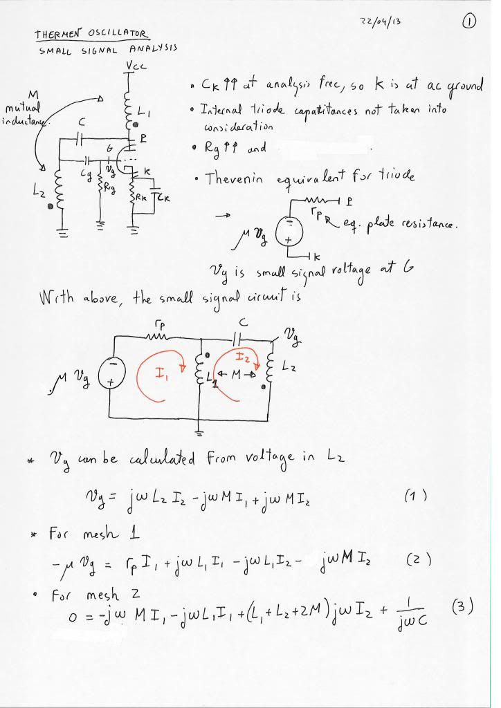
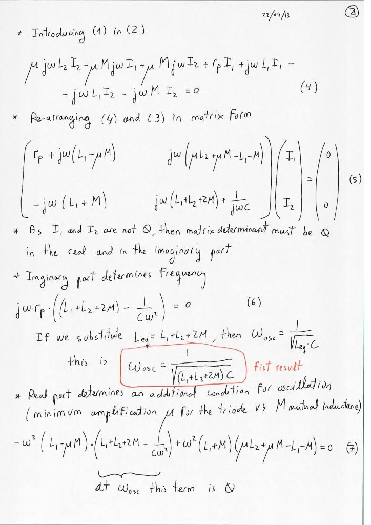
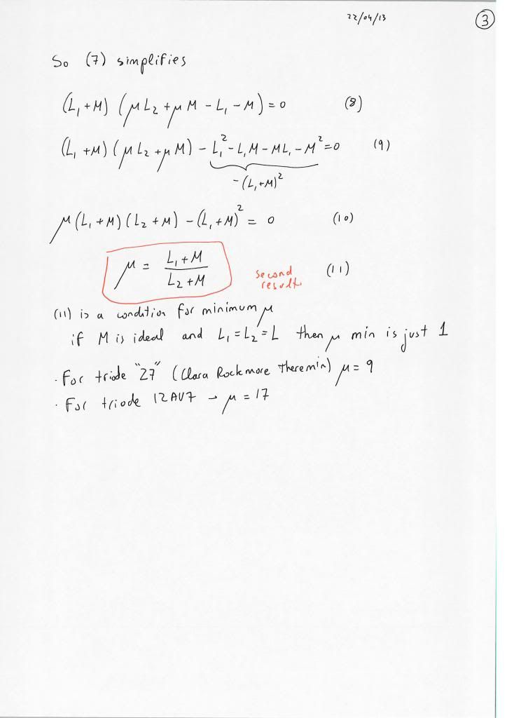
I have derived the the oscillation frequency and minimal mutual inductance/triode mu for the Thermen oscillator. Still this is the basic oscillator without the series antenna tank.

I have used a very simple small ac signal triode model (grid voltage dependent Thevenin voltage source). I think a more complicated model (adding interelectrode capacitances and other effects as winding resistances) is not really changing the basic results, but make the algebra much more complicated.

Really this small ac signal model for the circuit is not providing too much information. I have done it just for practice with the signs of the mutual inductances, that is a tricky thing. I hope everything is correct but perhaps some sign is wrong. The final results are OK (according RCA Radiotron).

I have handwritten the calculations, easier for me (more difficult for reading). So here is:

I do not know if this is of interest or it is just a little abstruse.

I have used a triode, but the results for a JFET are exactly the same. The mu of the triode is a normal characteristic referred on tube datasheets. It is not usually used for JFETs but it is just the result of multiplication of gm (transconductance) by rd (drain resistance) in the operating point. rp is the triode plate resistance, equivalent to this JFET rd drain resistance. For a normal triode mu goes from 10 to 100, depending on the triode type. Triode plate resistance rp is of the order of tens of kohms. For a signal JFET these figures are of the same order of magnitude: gm can be around 3-6 mS and rd around 20-40 kohm. Therefore the "mu" for a typical JFET can be around 20-50 (adimensional unit).

As far as rp (for triode) or rd (for JFET) is high in relation to resistances of the coils L1 and L2, the formula for the oscillation is good. Usually the resistances of the coils are some ohms, and rp-rd are tens of kohm, so the approximation is very good.

My intention is to apply the same small signal technique to the Thermen oscillator with the antenna series tank attached. Hopefully I'll get a formula for w=w(C-hand) in oscillation.

You must be logged in to post a reply. Please log in or register for a new account.