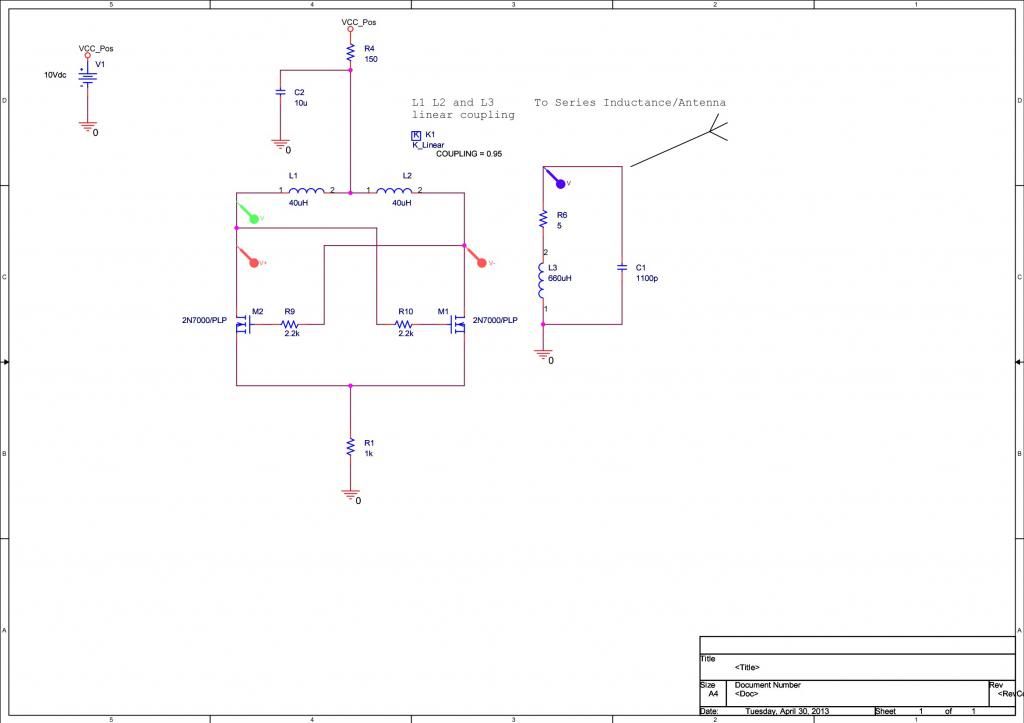
I have done a simulation of the topology I was trying to describe for the balanced oscillator:
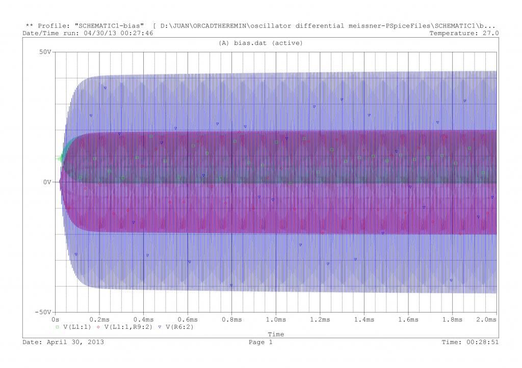
The oscillator starts easily in the simulation which is usually a proof that the circuit is really unstable.
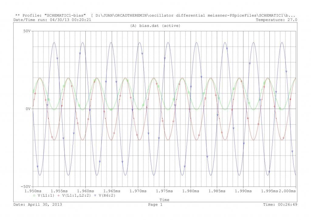
The tank L3-C1 is like a transformer secondary and is setting the oscillation frequency. I have chosen 660uH and 1100p for a frequency of approx 180kHz. The differential oscillator is very simple, using 2n7000 signal mosfets. Tail resistor is adjusted to have approx 6.7mA, so 3.3mA for each tail. The inductances L1 and L2 are not contributing to oscillation frequency, only coupling the feedback amplifier to the tank.
With the 10V supply, the sources are oscillating to 20Vpp (green), the balanced signal is 40Vpp (red) and the signal in the tank is 84Vpp (blue).
A rough calculation for a possible air coil: 4cm diameter tube, 160 turns in 4 cm long (in one or two layers) gives 660uH, and 35 turns in the same tube 2 cm long gives 40uH, so this could be a single layer of 70 turns center tapped. Of course the transformer could be wound in a ferrite.
Possible problems:
-The coupling must be high. As the determining oscillator tank in only magnetically coupled to the feedback amplifier, if the coupling is not good enough, probably the amplifier will go into parasistic very high frequency oscillations.
-In any case the L1, L2 coils are probably trying to oscillate with whatever capacitance is in their side. I think the circuit will be prone to high frequency oscillations, but probably this can be attenuated with some bypass capacitor to ground.
The good things:
-The signal mosfets are quite happy with the voltages, I think.
-Nice balanced signal (red) for a balanced mixer.
-The signal in the tank can be as big as we like, just adapting the inductances ratios, like in a transformer. 84Vpp is perhaps a little exaggerated, but I bet that signal was not lower in original tube theremins.
I have not found this topology in any book, so it can be called Balanced Meissner/Reinhartz oscillator or something like this. In any case, seems interesting, just for fun.
Juan