Tell us about your experience with Open.Theremin

Posted: 11/24/2013 7:10:20 PM
gaudi

From: Switzerland (CH)

Joined: 8/6/2010

This is what I get when I compare current OT schematic with your suggestion dewster. Suggestions for dimensioning ;-)

$

What I would like to improve on the open theremin is the tuning as many user have difficulties with the tuning of the heterodyne oscillators. And the smd tuning caps are so small. You mentioned Varicap, Fred. Is this the same as variable capacitance diodes. How to connect them - say in the circuit above ;-)

Urs

Posted: 11/24/2013 8:40:24 PM
dewster

From: Northern NJ, USA

Joined: 2/17/2012

gaudi, If people are having trouble with adjusting the heterodyning, I guess I'm not seeing how this will help much.  Here are some things I can think of that you might try:

1. Adjust the coil instead of the capacitance. 

2. Supply a variable heterodyning frequency from logic under software control.

3. Skip the heterodyning if you can come up with some way to measure the frequency of the oscillator directly (but I'm not sure how you would do that in a timely fashion given the low Arduino clock speed).

4. Use a PLL and look at the loop voltage with an ADC, this would help with the need for a quadrature detector in my oscillator circuit (but I haven't tried this, and I'm not sure if the 4046 VCO is stable enough or not).  This is analogous to what I'm doing digitally in an FPGA.

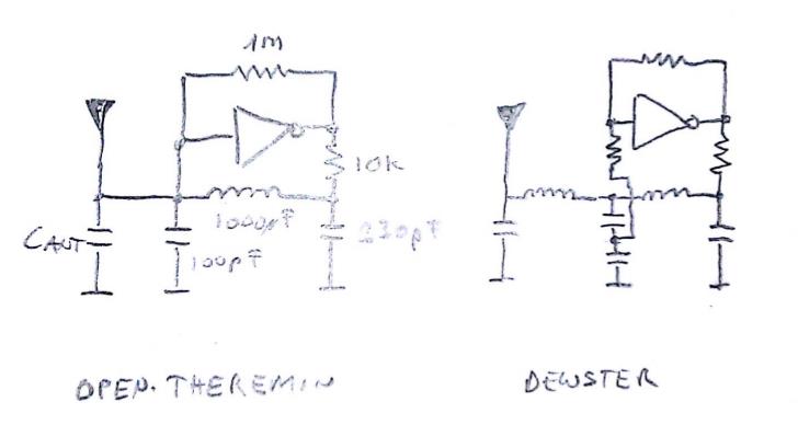
The oscillator you are using now looks like it probably has a fairly low Vp-p swing at the antenna.  And that 100pF from the antenna to ground can't be helping your sensitivity.  I'd lower the 10k to 1k or 470 ohms, replace the 100pF with a capacitive voltage divider (like in my circuit) with 10pF on the top and 470pF on the bottom (size the bottom capacitor to keep the voltage swing into the inverter comfortably within VCC and ground).  Size the remaining capacitor (220pF?) to give maximum amplitude at the input of the gate for your given antenna.  For more sensitivity stick an inductor in series with the antenna, roughly the same value as the one in the tank (if you do this you will probably need to resize the caps a bit).

You should probably think about protecting the CMOS from ESD.  You might look at the Littelfuse SP721 for this (seems to work in my unproven circuits, but who knows).  Connect a protection network to the gate input and maybe one to the gate output too.  Using an antenna series inductor probably helps with ESD.

Posted: 11/24/2013 9:19:11 PM
FredM

From: Eastleigh, Hampshire, U.K. ................................... Fred Mundell. ................................... Electronics Engineer. (Primarily Analogue) .. CV Synths 1974-1980 .. Theremin developer 2007 to present .. soon to be Developing / Trading as WaveCrafter.com . ...................................

Joined: 12/7/2007

Gaudi,

I think one of the main problems people have, is when they are trying to tune on the "wrong side" of the null point

To be honest, I have not studied your open.theremin stuff, and perhaps what I say wont work with that.. But on my SkyWave theremins I had a LED indicator - it went red when tuning was on the wrong side of null, and muted the theremin when in this state - LED went green and became unmuted when the player was on the 'right side' of null.

I simply repeatedly counted cycles from both the pitch and variable oscillators for a finite interval, and checked frequencies (which was higher) .. If the Ref oscillators frequency  was higher than the VFO, then I knew it was 'right side'  and if it was lower, then it was 'wrong side'.

Schematics. code (C) etc is here.

Fred.

Ps - your image isnt pointing to a url (?) - so we cant see it! ;-) ... or at least I cant ..

Posted: 11/24/2013 9:54:32 PM
dewster

From: Northern NJ, USA

Joined: 2/17/2012

Here you go Fred:

Posted: 11/30/2013 6:06:41 PM
ILYA

From: Theremin Motherland

Joined: 11/13/2005

I have calculated the pitch curves for different calibrations of Open.Theremin.UNO (v1.2.)
(the hand is 1.85, 1.5, 1 and 0.54 m away from the antenna).

The data "Chand vs distance" are taken from the dewster's Excel sheet.
Also it is assumed that the resonance circuit of oscillator consists of a single inductance and capacitance.
"pitch_v" and "add_val" are variables from software.

 
Hope this will be interesting.


Posted: 11/30/2013 7:00:32 PM
ILYA

From: Theremin Motherland

Joined: 11/13/2005

And how inductance will be affect on pitch (thermal stability):


Posted: 11/30/2013 9:03:53 PM
dewster

From: Northern NJ, USA

Joined: 2/17/2012

"I have calculated the pitch curves for different calibrations of Open.Theremin.UNO (v1.2.)"  - ILYA

Interesting.  Do you see any attempt at linearization in the software?

"And how inductance will be affect on pitch (thermal stability)"

Do you know what temperatures might be associated with those curves?

Posted: 12/1/2013 4:31:57 PM
ILYA

From: Theremin Motherland

Joined: 11/13/2005

If the specific dependence (calculation "input period" to "audio freq") consider as an "attempt at linearization" then yes.

A measured period of input frequency pitch_v (in ticks of 16MHz) puts into  formula
add_val=(pitch_init-pitch_v)/2+200,
  where
  pitch_init  is a value at calibrating (around 26000),
  add_val is a phase increment for DDS (direct digital synthesis).

The DDS uses sample rate 31250 sps and a 16-bit  phase accumulator so the output audio frequency will be
Faudio= add_val*31250/65536


I have not information about thermal stability of Bourns coils.
Assuming that the thermal coefficient is 10-5 the curves above are shown with 10C interval.

PS. In some of Murata' pdf I found the value of 430 ppm, i.e. 43*10-5 [C-1]. For this case the step is 0.23C.

Posted: 12/1/2013 6:52:43 PM
dewster

From: Northern NJ, USA

Joined: 2/17/2012

"If the specific dependence (calculation "input period" to "audio freq") consider as an "attempt at linearization" then yes."  - ILYA

Hmm.  Adding a static number to compensate for the heterodyne offset makes sense.  I guess I meant more of a dynamic linear or polynomial interpolation of pitch_v to produce the add_val DDFS input. 

"PS. In some of Murata' pdf I found the value of 430 ppm, i.e. 43*10-5 [C-1]. For this case the step is 0.23C."

Yikes! 

The lack of ferrite material / temperature dependence info for various chokes has driven me away from most commercial offerings.  Miniature types are likely quite terrible with temperature due to size constraints (high permeability with no air gap) - they're chokes, not precision resonant inductors.  The ones used in the Open.Theremin are fairly low Q as well (30 IIRC).

Posted: 12/2/2013 11:33:12 PM
RoyP

From: Scotland

Joined: 9/27/2012

Just like to report that I have been playing the OT with the Polyphonic software loaded and it really does what it says!

One thing I forgot to mention was that I had some concerns over how close the antennae terminals on the OT board were, given that it's generally regarded the terminals (and by imlication the antennae) should be as far apart as possible. I was doing this to see how big the housing should be when I built it. To test how far they could be before interfering with one another, I deliberately started off with the worst case scenario and twisted the antennae wires from the OT board around each other before connecting them to their respective antenna and found, to my astonishement, that it had no degrading effect on the performance!

The OT might not be perfect but it's throwing up some surprises :-)


You must be logged in to post a reply. Please log in or register for a new account.