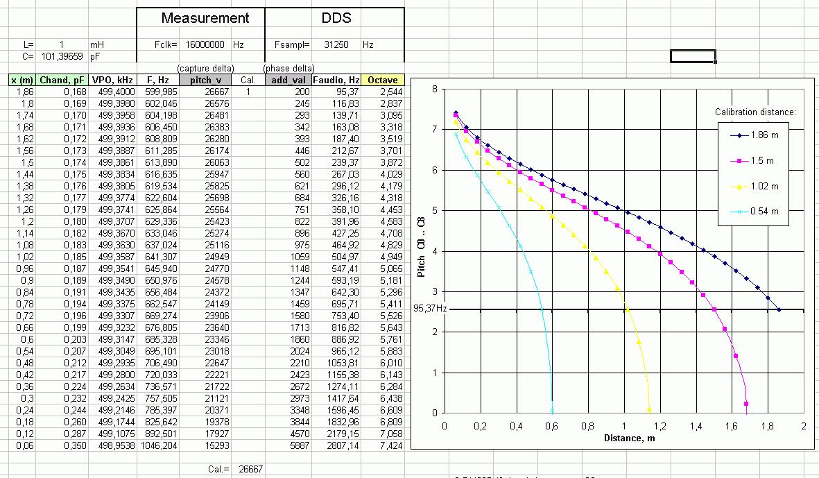
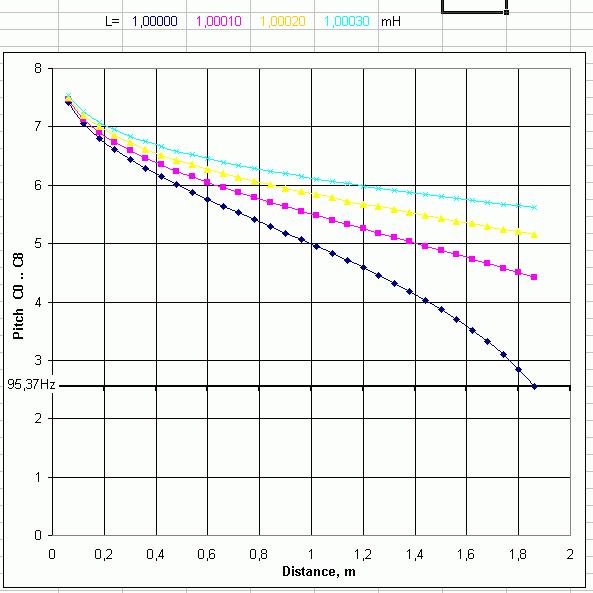
gaudi, If people are having trouble with adjusting the heterodyning, I guess I'm not seeing how this will help much. Here are some things I can think of that you might try:
1. Adjust the coil instead of the capacitance.
2. Supply a variable heterodyning frequency from logic under software control.
3. Skip the heterodyning if you can come up with some way to measure the frequency of the oscillator directly (but I'm not sure how you would do that in a timely fashion given the low Arduino clock speed).
4. Use a PLL and look at the loop voltage with an ADC, this would help with the need for a quadrature detector in my oscillator circuit (but I haven't tried this, and I'm not sure if the 4046 VCO is stable enough or not). This is analogous to what I'm doing digitally in an FPGA.
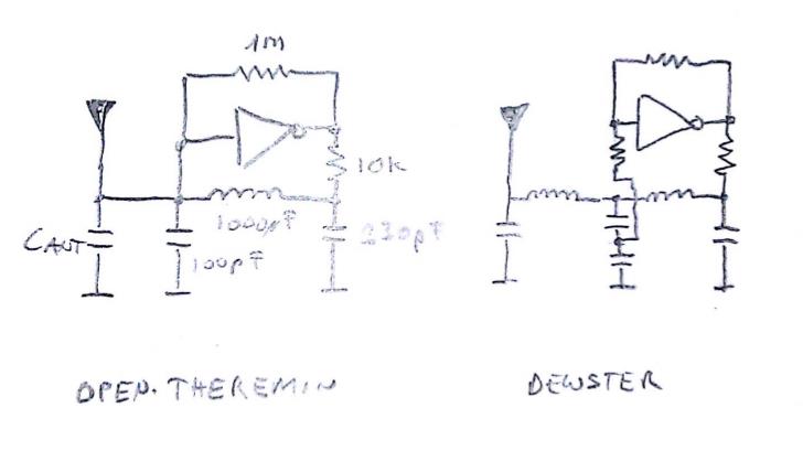
The oscillator you are using now looks like it probably has a fairly low Vp-p swing at the antenna. And that 100pF from the antenna to ground can't be helping your sensitivity. I'd lower the 10k to 1k or 470 ohms, replace the 100pF with a capacitive voltage divider (like in my circuit) with 10pF on the top and 470pF on the bottom (size the bottom capacitor to keep the voltage swing into the inverter comfortably within VCC and ground). Size the remaining capacitor (220pF?) to give maximum amplitude at the input of the gate for your given antenna. For more sensitivity stick an inductor in series with the antenna, roughly the same value as the one in the tank (if you do this you will probably need to resize the caps a bit).
You should probably think about protecting the CMOS from ESD. You might look at the Littelfuse SP721 for this (seems to work in my unproven circuits, but who knows). Connect a protection network to the gate input and maybe one to the gate output too. Using an antenna series inductor probably helps with ESD.
$


