Possibly a "new" theremin topology, and links to related background

Posted: 12/1/2013 6:42:29 AM
FredM

From: Eastleigh, Hampshire, U.K. ................................... Fred Mundell. ................................... Electronics Engineer. (Primarily Analogue) .. CV Synths 1974-1980 .. Theremin developer 2007 to present .. soon to be Developing / Trading as WaveCrafter.com . ...................................

Joined: 12/7/2007

A number of threads are ongoing at the moment, which IMO have common subject matter - I have found it difficult to keep these threads "in my mind" and find myself needing to go looking for "background" data to understand whats being said currently -

I have presented what I think may be a new theremin topology, but "published" this on Dewsters  "Let's Design and Build a (mostly) Digital Theremin!" thread, and dont feel that I should hijack this thread anymore - I may add loads more stuff on that here.. Also, just as I find it difficult to locate things posted in an "off topic" location, others may find locating this topology difficult in a thread presently at 39 pages long...

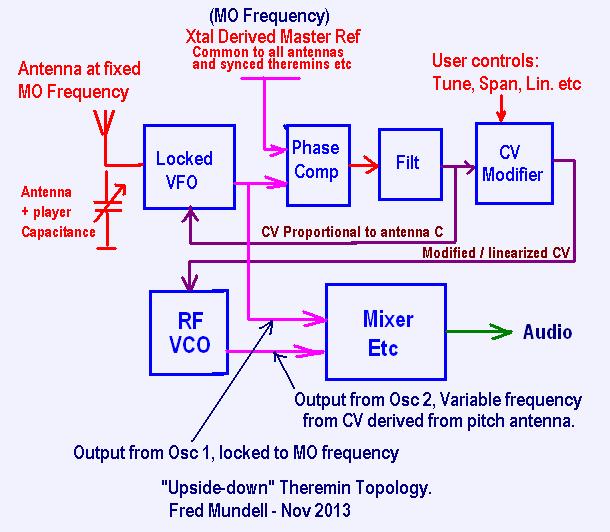
>> Link to first disclosure at TW of my proposed theremin topology on Dewsters "Digital Theremin" thread <<  Full details can be found in pages 37 to 39 of this thread.. Below is the block diagram of this topology:

The matters I have found most interesting and possibly related were Dewsters ideas on his AFE (Analogue Front End) for his Digital Theremin, and in particular his series LC oscillator and "tankless" ideas.

It all starts here (well, actually, it probably starts early in the wonderful "Digital Theremin" thread: "Tanks" For Nothing!" (but this thread IMO loses direction)

Then some more discussion on CMOS oscillators and particularly Series vs Parallel  - This is where I thought that Dewsters oscillator may be a good choice for my new "upside down" topology..

"Tell us about your experience with Open.Theremin  Page 3 to 5"

And then moved into "Let's Design and Build a (mostly) Digital Theremin! Page 37 to 39" 

This thread is a sort of continuation from where I left off there - but this does not mean I have 'left' that thread, just that I dont want to put any more OT stuff on it!

At this time I am at the design and simulation stage of my "Upside Down" theremin, NOTHING has been physically built! -

I will publish everything here - I think a lot of stuff (with adaption) may be of use for both analogue and digital theremins.. In particular, I think that my foray into a perhaps novel means of electronic tuning (utterly inspired by Dewsters ideas) may hold a lot of promise.

Fred

Ps - Last time I used the word "new" in a posting on this forum, I got jumped on by the "heavy's"   -- "its not new, its used in GHz oscilloscopes" "its a simple heterodyning mixer" and other similar BS -

So let me just say this once - unless you can show me a THEREMIN that uses this topology, or a prior publication of this idea FOR THEREMINS,  PLEASE SHUT UP!!!!! - I REALLY get pissed off by some people here who have little imagination, but seem to get off on discouraging those who think "out of the box".

I fully accept the possibility that someone else may have published or implemented "my"  "upside down" theremin idea before me, and if you are aware of someone having done this,  I want to know.. But dont go telling me its not "new" because (for example) something which may similar is being used in some communications reciever or submarine sonar system!

Also, I really am not interested in anyone from TW (or elsewhere) , who has not produced, displayed, published or discussed this idea PUBLICLY, claiming that they have been working on this idea before me.  If you do stuff in secret, and someone publishes or patents the idea before you, well - tough luck!  -  If I am the first to disclose an idea, then I deserve the credit ! (for what thats worth - which is mostly nothing)

One reason for publishing ideas is to place them firmly in the public domain, so that they cannot be patented by anyone. Another reason is so that, even if I am never able to bring the ideas to production, the time I spent might not be completely wasted - Someone else may, at some future time, make use of them.

Posted: 12/1/2013 12:48:49 PM
Thierry

From: Colmar, France

Joined: 12/31/2007

Fred, if you are really interested please have a look into a Moog Series 91 theremin. Parts of your topology can ce found there: The Xtal master oscillator, the locked VFO, the phase comparator, the filter and the CV modifier.

But then there come the differences: In the Series 91 the modified CV is used to drive directly an AF oscillator around an OTA plus Schmitt-trigger before the wave shaping is applied. Thus your topology which adds true heterodyning risks to give a more genuine theremin feeling to the player.

After what Masami Takeuchi told me without entering too much into details, his new "Gordin Masazane Theremin" uses a topology which he says being an evolution from the Series 91. So it is highly probable that it resembles your topology also at least a little bit.

Posted: 12/1/2013 2:04:09 PM
FredM

From: Eastleigh, Hampshire, U.K. ................................... Fred Mundell. ................................... Electronics Engineer. (Primarily Analogue) .. CV Synths 1974-1980 .. Theremin developer 2007 to present .. soon to be Developing / Trading as WaveCrafter.com . ...................................

Joined: 12/7/2007

Thank you Thierry,

Yes, I know the CV route - I had adopted this method for most of my designs which required constant frequency antennas to avoid interactions (the Epsilon for example).. With these, one pumps a constant frequency into an antenna resonator, and gets a result (voltage or whatever) proportional to the antenna capacitance (due to the resonators frequency being altered).. I have also used this to implement volume circuits where the reference frequency drives the volume antenna, so there is no possible interaction with the pitch oscillator.

I didnt know the 91 used a VFO and phase comparator - Have never seen a schematic for the 91 or inside one - if anyone knows where I can get this I would love to see it!

There isnt, as you say, that much difference between the two topologies - but the major difference is that, with my new topology, I think it will be easier to shape the linearity response, and also much easier to have a true heterodyning theremin.

This present route is a bit ironic for me - I had been going down a purely CV route, with the front-end producing 1V/Octave output, and I had designed (and prototyped) some HF VCO's that accepted 1V/Octave and produced audio responding accurately to 1V/Octave when mixed with a specific frequency reference oscillator.. But the problem is the expense of these - Each oscillator requires a PLL to multiply its frequency 10*, and a pitch-to-voltage converter working on the resultant (mixed) audio, so it can be compared to the incoming 1V/Octave, and a frequency correction voltage fed back to the variable HF oscillator.. It a design requiring a big PSoC to implement the analogue and logic.

This new route, whilst still not 'elementary', is a lot cheaper - And I can (with an additional module) still provide the fast  1V/Octave (which can resolve down to 16Hz in about 2ms) output to drive conventional CV synth modules, but simultaniously have true heterodyning voices in the theremin.. *The only disadvantage is that these voices wont accept a 1V/Octave drive from other equipment.. Which is a bit of a bummer, as I was hoping to have a true theremin capable of MIDI record / Replay (Yeah, I know what ive said about MIDI - But when someone with money wants something, and you need the money.... )

Fred.

*Its great how writing things down often leads to solutions - I cant count how many times I have written a long blurb for TW, then just before clicking "send" I see a whole new angle on the matter, and often never get to clicking send - but just save the posting for my reference..

I have just seen a way to solve this issue without adding much - been thinking about it for weeks and come up with nothing till now ;-)

Posted: 12/1/2013 4:42:04 PM
Thierry

From: Colmar, France

Joined: 12/31/2007

Unfortunately I could never put my hands on the Series 91 schematics. But I had the luck to be asked to check and to service several of these beasts (3 from Switzerland and 1 from France) which allowed me to understand their principle of operation.

I was very surprised when I found for the first time that the pitch oscillator ran on constant frequency.  

Later I got a copy of the user's manual from which I may cite:

"TECHNICAL DESCRIPTION: The Series 91 circuitry is divided into two separately operating parts: Control and Tone Generating. 

Control 

The control (antenna) circuitry consists of two specially designed antenna coils that form resonant circuits with the antennas themselves. The pitch antenna circuit is excited with a 263 kHz signal, while the volume antenna circuit is excited with a 461 kHz signal. The effects of the proximity of the player's hands are measured by phase and amplitude detection circuits that are coupled to the antenna coils. 

RESPONSE SPEED: Pitch and volume of tone respond essentially instantly (delay time less than two milliseconds) to the motions of the player's hands. 

Tone Generating 

The tone generating circuitry uses contemporary analog synthesizer technology to emulate the waveforms of Professor Theremin's instruments. 

TIMBRES: A selection of four discrete timbres is available. Timbres vary in brightness, but conform to the spectral characteristics of Leon Theremin's designs."

Posted: 12/1/2013 7:09:10 PM
dewster

From: Northern NJ, USA

Joined: 2/17/2012

"One reason for publishing ideas is to place them firmly in the public domain, so that they cannot be patented by anyone. Another reason is so that, even if I am never able to bring the ideas to production, the time I spent might not be completely wasted - Someone else may, at some future time, make use of them."  - FredM

Hear, hear!  Some information is too valuable to not give away. ;-)

Posted: 12/1/2013 8:50:02 PM
FredM

From: Eastleigh, Hampshire, U.K. ................................... Fred Mundell. ................................... Electronics Engineer. (Primarily Analogue) .. CV Synths 1974-1980 .. Theremin developer 2007 to present .. soon to be Developing / Trading as WaveCrafter.com . ...................................

Joined: 12/7/2007

"The pitch antenna circuit is excited with a 263 kHz signal, while the volume antenna circuit is excited with a 461 kHz signal. "

Thank you, Thierry -

But this puzzles me profoundly.. Why, if one has a Xtal reference oscillator, and goes to the trouble of having a phase-locked fixed frequency pitch oscillator (locked VFO) and related  pitch antenna...

Why then have a seperate frequency for the volume circuitry ???  - As I see it (and I have found these excellent topologys in practice) there are two great ways to do the volume circuit..

1:) The simplest can use a conventional theremin topology, but implement all pitch tuning on the pitch VFO or antenna resonator - one then has a stable fixed frequency reference and can use this (or a 2* multiple derived from this) with a volume antenna resonator and either detect amplitude or phase (or both) to derive the volume CV.

2:) Simply repeat the pitch locked VFO scheme to derive a volume CV - if one has a Xtal oscillator anyway.

Bob Moog was not the sort of engineer who would have been likely to overlook these possibilities - his designs tend(ed) to be quite minimalist, and I am inclined to think he must have had (or believed he had) good reasons for his choice.... But Im damned if I can see them!

To me, having seperate assynchronous oscillators for pitch and volume is a pain, and just invites difficulty - And from my expierience, implementing volume circuits whose frequency is locked to the the same fixed reference frequency as is used by the mixer overcomes all the problems.. The cheapest and most reliable volume circuits I have used have just been a buffered reference oscillator driving a series volume antenna LC, and deriving the antenna current (or amplitude) to produce the volume CV.

The only tiny down side of the above is that you cannot implement tuning on the reference oscillator (because it is shared by both pitch and volume circuits) so must tune either the pitch oscillator or (better) the pitch antenna resonator - The volume circuit tends to be less critical, so one can usually get away with slug-tuning the resonator, then adjusting the CV bias to implement user 'tuning' (and gain if you have adjustable span).

I also notice the word "excited" - To me, this implies perhaps something other than oscillators.

I have designed and played with fixed-frequency circuits and topologies more than with any other theremin related matter - Early in my messing with theremins (before I had even seen a theremin live or played a "real" one) I was looking at multi antenna stuff producing CV's for 3d operation. I started with PSoC CapSense, but soon found it unsuitable (particularly after I had actually seen Lydia play and started playing myself) and went back to standard LC, and attempted to multiplex VFO driven antennas - quickly moving to fixed frequency driven antenna LC topologies.

Whoever did the Moog Poly-Theremin script had, I suspect, looked at the idea seriously at some time.. The "Iso-synchronous" in the "IDIOT" gives me this feeling ;-)

Fred.

Posted: 12/1/2013 9:22:54 PM
Thierry

From: Colmar, France

Joined: 12/31/2007

There are not two separate asynchronous oscillators for pitch and volume. There is one single 1.8432 MHz xtal oscillator. The reference signals for volume and pitch are obtained through dividing by 4 and by 7.

Pitch and volume tuning in the Series 91 theremins is done through variable capacitors (air, 3 gang) in the antenna resonant circuits.


The Moog Series 91 partly disassembled


The RF oscillator and control board


CV processing, sound generator, wave shaping, VCA. The CEM 3340 is a synthesizer chip, an analogue oscillator with integrated lin/exp current converter. The CD4016 analogue switches are for the timbre setting. The LM13600 has the "classical" task to do the wave shaping and plays the VCA role as in the Etherwaves.


Power supply and 10W audio amplifier for the integrated speaker. 7812 and 7912 positive and negative voltage regulators for the other boards. LM1875 integrated audio amplifier.

Posted: 12/1/2013 11:59:05 PM
FredM

From: Eastleigh, Hampshire, U.K. ................................... Fred Mundell. ................................... Electronics Engineer. (Primarily Analogue) .. CV Synths 1974-1980 .. Theremin developer 2007 to present .. soon to be Developing / Trading as WaveCrafter.com . ...................................

Joined: 12/7/2007

"There are not two separate asynchronous oscillators for pitch and volume. There is one single 1.8432 MHz xtal oscillator" - Thierry

Ok, thanks Thierry - they are locked together, that makes sense!

Great pictures - with time one could almost produce a schematic from them. A CEM 3340! Wow! - I am truly shocked - I never realized Moog used those parts - always thought his synths used his own designs! - Oh, the 3340 was a wonderful IC, made analogue poly synths affordable because the on-chip exponential  converters were so good.. I have 2 polysynths which use them.

IMO its a bit of a shame that this sort of information only comes out rarely - Please, Thierry - I am sure there are many people here who would love to see inside some of the rarer theremins, and / or  get your insights on them... Why not start a "Inside theremins" thread where you occasionally feed us this stuff ? - Someone looking for this data may not find it in this thread - but if there was a thread that we could go to, that would be great! .. Start such a thread, and move those photos there!

Fred.

Posted: 12/2/2013 12:12:10 AM
dewster

From: Northern NJ, USA

Joined: 2/17/2012

"Why not start a "Inside theremins" thread where you occasionally feed us this stuff ? - Someone looking for this data may not find it in this thread - but if there was a thread that we could go to, that would be great! .. Start such a thread, and move those photos there!"  - FredM

Yes, that would be great!  Kind of like my "Nekid Pichures" thread over on Piano World for digital pianos (and such):

http://www.pianoworld.com/forum/ubbthreads.php/topics/1761142

(My posts are the RD-700NX, AN1x, and P120 - and soon to be P105)

That's a beautiful pitch coil in the 91.  Those logic / analog boards are a real throw back.

Posted: 12/2/2013 8:02:58 AM
FredM

From: Eastleigh, Hampshire, U.K. ................................... Fred Mundell. ................................... Electronics Engineer. (Primarily Analogue) .. CV Synths 1974-1980 .. Theremin developer 2007 to present .. soon to be Developing / Trading as WaveCrafter.com . ...................................

Joined: 12/7/2007

Hey, thats one cool thread Dewster! ;-)

"Those logic / analog boards are a real throw back."

Yeah! ;-) .. Must admit that I am deeply unimpressed by the layouts! - That PSU card is just shocking! - I can understand the thin tracks and lack of ground planes on the other boards, but the PSU should be chunkier even if it only supplies low current ... (also, minimal etching is more environmentally friendly).. That board could be half the size, packed with copper, and be forward to clear the pitch antenna so the extra copper's effect was reduced.

[OT]..

I have a pile of synths / keyboards I need to get up and running (many have been bought for peanuts, dysfunctional, and stored in my loft awaiting repair) - Just to add to those, several of my loved keyboards have gone faulty (Disk drive on my PDP400 and Karma both died in the same week, and my AX73 also died recently) - I recon I can probably sell my junk keyboards for about £3k when they are repaired (some are ancient rare synths, like the Farfisa SynthOrchestra, Siel Cruise, old Juno 6, other Roland Analogue poly's,Moog Prodigy, analogue MIDI expanders, Sequencers....)

So I may have some Nekid pictures to add to your collection soon ;-)

Fred.

(if you know of any photos / instructions / service manual for the Yamaha PDP400  please let me know - I want to give it a full service when I pull it apart - I love the feel of this keyboard, its sort of semi-weighted and is my master MIDI controller - sounds are also ok-ish.. I like the feel better than that of my Clavinova I sold, and a lot more than I liked the feel of my Roland MKB-800 Master Keyboard I sold - Both of those keyboards actions  were too heavy for me)

You must be logged in to post a reply. Please log in or register for a new account.