Let's Design and Build a (simple) Analog Theremin!

Posted: 10/24/2020 7:59:22 PM
Buggins

From: Porto, Portugal

Joined: 3/16/2017

Thank you, Mark!

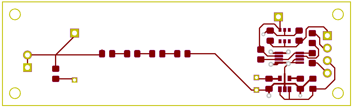
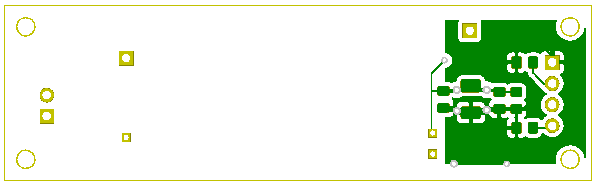
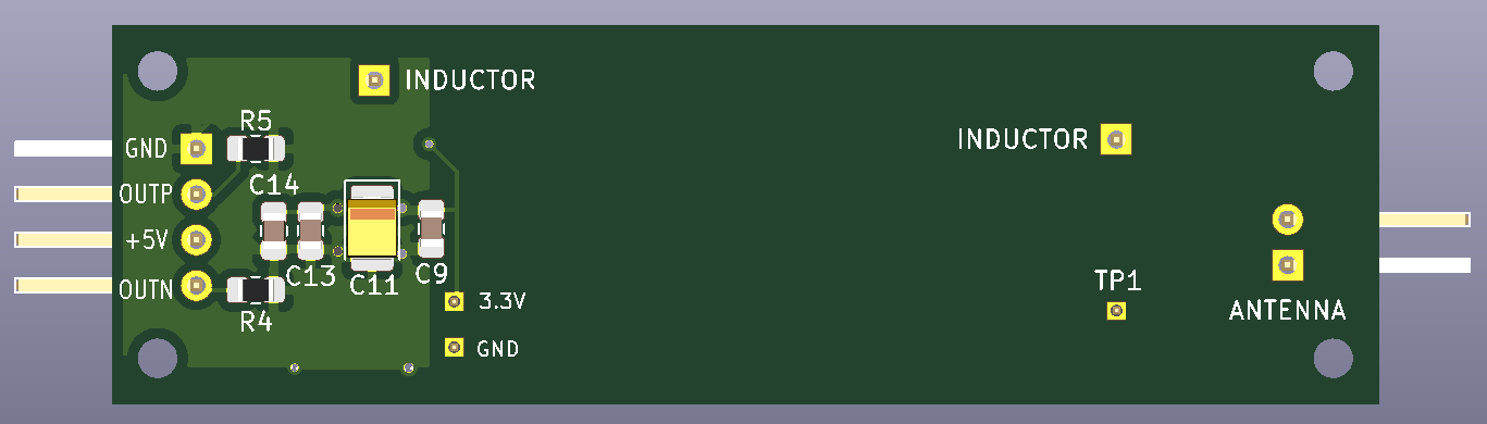
So, putting all bypass caps on bottom side seems ok.
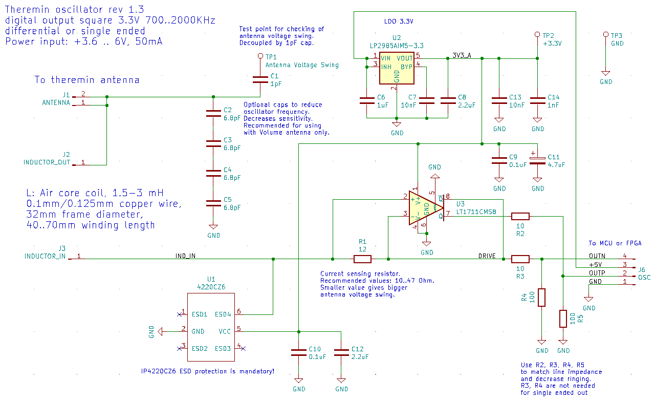
I wanted to ask if order of caps in chain does matter, but it looks like you already answered. Lower value capacitors should be connected with shorter path to IC pins, while larger can be located at bigger distance. 
Better design would have isolated island surrounding comparator and its bypass caps with two entry points. 
Filling top area with Vcc instead of GND may form small but fast bypass cap on power line.
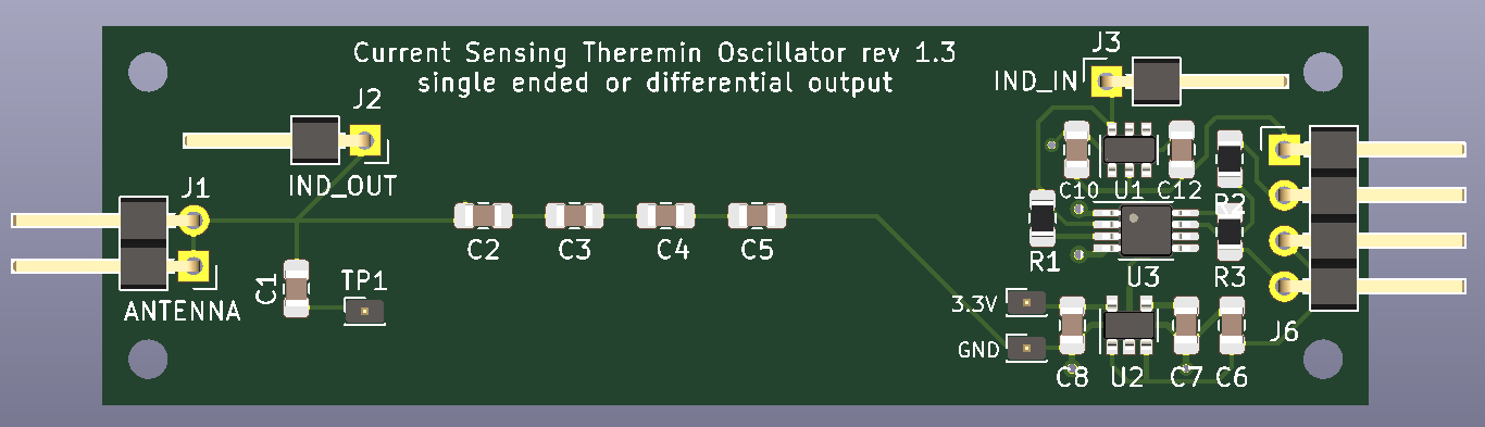
Next time I will try to take it into account. I will correct it in next revision of this PCB.

Meanwhile, I've already ordered manufacturing of PCBs using recent layout I've published.

Posted: 10/30/2020 4:39:29 PM
markallie

From: Madison, WI

Joined: 5/19/2016

Great. I'm assuming it will work. There seems to be a good isolation of the inputs from the output currents. Bypass is better than most designs I've seen that actually work. Who do you use for PC boards?

Mark Allie

Posted: 10/30/2020 7:39:25 PM
Buggins

From: Porto, Portugal

Joined: 3/16/2017


Great. I'm assuming it will work. There seems to be a good isolation of the inputs from the output currents. Bypass is better than most designs I've seen that actually work. Who do you use for PC boards?

Mark Allie

Unfortunately, I've found bug in previous revision of PCB: when positive input is after R_sense, and negative is before R_sense,
L should be driven by negative output of comparator. In revision 1.2, it's fed by positive output. So, PCBs which are manufactured and in delivery cannot be used unless track from positive output is cut and negative one is soldered as inductor drive instead.

Designed and ordered new version (rev 1.3) today.
I'm ordering PCBs from pcbway.com - 10pcs of small PCB like this oscillator costs $5 + $6 for delivery.


KiCAD schematics:


Differential output mode is now available. For single ended output mode, 3-pin connector with the same pinout as in previous version can be soldered.
For both outputs resistors are routed. Serial, pulldown or both resistors can be used to match line impedance.
When output resistors not used, serial resistors can be replaced with wires.

PCB:


Sample usage of oscillator differential output with filter for ADC (+-500mV, sine with -45dB 3rd harmonic).

Suitable for feeding of 100MHz 8bit ADC AD9283BRSZ-100 for FPGA based implementation I want to try.

Model is available here

Posted: 11/2/2020 11:26:27 PM
markallie

From: Madison, WI

Joined: 5/19/2016

OK waiting to hear how it goes. I use PCBWay as well. PCB's are OK if you don't modify them too much. This is the place I use for the PCB's I use in the Theremin course I teach at the university. They work for most students.

Mark Allie

Posted: 11/15/2020 5:50:36 PM
dewster

From: Northern NJ, USA

Joined: 2/17/2012

Differential Oscillator - Update

Vadim came up with the good idea of using a current mirror for the differential pair sink rather than a resistor.  I was able to re-use the coil drive current mirror here with good results both in sim and on the bench, so it's 6 transistors and 6 passives (not counting the inductor):

It seems to oscillate better with larger area antennas (needs some minimum C for full swing), though there may be something of a sweet spot.  A 10mm diameter x 350mm rod doesn't give full voltage swing unless my hand is near.  A 10mm diameter x 500mm rod gives the full swing of >100Vp-p.  A 115mm x 235mm plate similarly give full voltage swing, as does a 20mm diameter x 500mm rod. 

It doesn't stall when I touch a painted plate antenna.  It does stall when I touch the bare metal, but it starts right back up again.  With a 3.3V supply it draws 4.9mA average.

Interestingly, my D-Lev P2 is about 2' away and the pitch oscillator similarly utilizes a 4mH inductor, and whichever oscillator is running first "wins".  If I fire up the D-Lev afterwards, this oscillator messes with the pitch side enough that I can't play it.  But if I fire up the D-Lev first then the D-Lev is fine but this oscillator bobbles all over the place.

[SPICE] (these oscillator sims seem to be especially popular downloads, 100's each)

Posted: 11/16/2020 2:02:52 PM
Buggins

From: Porto, Portugal

Joined: 3/16/2017


Vadim came up with the good idea of using a current mirror for the differential pair sink rather than a resistor.  I was able to re-use the coil drive current mirror here with good results both in sim and on the bench, so it's 6 transistors and 6 passives (not counting the inductor):
-- dewster

It still can be simplified. 3 resistors and 1 cap are not needed.
Voltage swing on antenna is 60-100Vpp depending on coils and antenna capacitance.

(Btw, dewster, you didn't set serial resistance and parallel capacitance for inductor).

Tried to optimize - keep it oscillating with high antenna cap (200pF) and low Rrf (470K, but with bigger C_ant, it can work down to 10K) - simulation of hand touch.

LTSpice model file is here

Posted: 11/16/2020 5:56:21 PM
dewster

From: Northern NJ, USA

Joined: 2/17/2012

"It still can be simplified. 3 resistors and 1 cap are not needed." - Buggins

I agree that the elimination of the collector resistor is an improvement and simplifies things.  But I like the current mirror 0.01uF capacitor because it smooths out current draw.  And the current mirror 100 ohm lowers the overall current draw.

I think a good goal is to minimize the average oscillator current draw because that minimizes heating issues.  Mine draws ~5mA in real life, yours here draws ~13mA average in simulation.  I also look at currents through various components in the sim and minimization there is good too I think.

"Voltage swing on antenna is 60-100Vpp depending on coils and antenna capacitance."

On the bench with my circuit from yesterday I'm seeing 10.7 Vp-p through a 1pF cap, which means over 100Vp-p at the plate (scope 10x probe is >10pF).  With your circuit on the bench I'm seeing less voltage (maybe 1/2 that) and non-starting issues.

"(Btw, dewster, you didn't set serial resistance and parallel capacitance for inductor)."

Ah, thanks!

"Tried to optimize - keep it oscillating with high antenna cap (200pF) and low Rrf (470K, but with bigger C_ant, it can work down to 10K) - simulation of hand touch."

This oscillator topology seems to require a certain amount of antenna C to develop maximum antenna voltage.

Posted: 11/16/2020 8:41:34 PM
Buggins

From: Porto, Portugal

Joined: 3/16/2017


I agree that the elimination of the collector resistor is an improvement and simplifies things.  But I like the current mirror 0.01uF capacitor because it smooths out current draw.  And the current mirror 100 ohm lowers the overall current draw.

I think a good goal is to minimize the average oscillator current draw because that minimizes heating issues.  Mine draws ~5mA in real life, yours here draws ~13mA average in simulation.  I also look at currents through various components in the sim and minimization there is good too I think.

== dewster

Agree regarding current mirror resistor and cap.

Do you think heating of from 15mA current may affect stability of oscillator?

Can 35-45 mA on power input (10 mA avg on each output) affect comparator based oscillator stabiliy?
I planned to use shielded twisted pair with differential signal terminated from both ends by 100 Ohm resistors and LVDS receiver to get rid of noise which could be introduced on the way from oscillator to MCU.
How can change of temperature affect frequency? By changing of comparator delay?

LTC6752 (2.9ns propagation delay) works fine in LTSpice simulation (if you need single ended output).
It's faster than LT1711 and probably cheaper. LT1711 has 5.5ns propagation delay.

LTC6754 (1.8ns propagation delay) is working in LTSpice as well. It has LVDS outputs which is great if you are going to use LVDS receiver on MCU/FPGA input.
But when loaded with 100 Ohm terminating resistor between outputs to match twisted pair impedance, voltage swing on outputs drops to 350mV which is good for LVDS receiver, but reduces voltage swing on antenna to 25Vpp.


Posted: 11/17/2020 11:32:08 AM
dewster

From: Northern NJ, USA

Joined: 2/17/2012

"Do you think heating of from 15mA current may affect stability of oscillator?"  - Buggins

Hard to say, but once you find an oscillator that gives you HV and doesn't flutter around, the next thing you want is one that doesn't drift around for too long after power-up.  Maybe it's too much of a knee jerk on my part, but I tend to see excessive current in an LC oscillator as potentially problematic.

"Can 35-45 mA on power input (10 mA avg on each output) affect comparator based oscillator stabiliy?"

I guess you'll find out!

"I planned to use shielded twisted pair with differential signal terminated from both ends by 100 Ohm resistors and LVDS receiver to get rid of noise which could be introduced on the way from oscillator to MCU."

I know how you feel about this, I was quite concerned about signal integrity at the interconnect too.  But single-ended through ribbon cable (with every other wire a ground) seems to work fine.  A 100 ohm or so drive resistor keeps the edges from ringing too much.

"How can change of temperature affect frequency? By changing of comparator delay?"

Yes, silicon delays are hugely influenced by temperature, so any actives in the feedback path can lead to drift.

Posted: 11/17/2020 5:35:00 PM
JPascal

From: Berlin Germany

Joined: 4/27/2016

I guess there will be hum collected over antenna and high-impedance coil to the transistor basis. When will you build this for testing?

You must be logged in to post a reply. Please log in or register for a new account.