Let's Design and Build a (simple) Analog Theremin!

Posted: 11/17/2020 7:36:19 PM
Buggins

From: Porto, Portugal

Joined: 3/16/2017


I guess there will be hum collected over antenna and high-impedance coil to the transistor basis. When will you build this for testing?
-- JPascal

If main hum noise collected via antenna is bigger than one which may be introduced with oscillator to main board connection,
my attempt to implement noise protected connectivity using shielded twisted pair and lvds differential line will be useless.

I hope that absolute main hum level remains the same when antenna swing is being increased, so changing antenna swing from 50 to 200V should increase effective sensing range by 10cm.

I'm waiting for delivery of ordered LT1711 comparator based oscillator PCBs.
I've received ordered LT1711 ICs, but their package is inconvenient for soldering on prototype board, so I will wait for PCBs.

Posted: 1/1/2021 3:57:37 PM
dewster

From: Northern NJ, USA

Joined: 2/17/2012

Transimpedance LC Oscillator

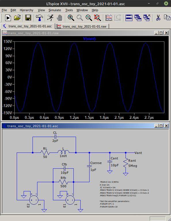
I'm a borderline idiot: just yesterday I realized that a transimpedance amplifier gives a fairly exact 90 degree phase shift over a rather wide range of input frequencies.  So it could be used to sense LC oscillation and then generate the coil drive.  Here's a toy circuit that demonstrates how it works:

The full LC tank voltage swing produces a current in Csense.  This is countered by the negative E1 feedback of Rfb and Cfb, which produces a virtual ground node at their intersection (the negative input of E1).  E2 provides an additional 180 degree phase shift, along with more gain to square up and stabilize the drive amplitude.  I've limited the internal E1 and E2 gains here to 10, which IIRC is in the ballpark of a high speed CMOS inverter.

I think it's better to sense the tank oscillation via a sensitivity killing virtually grounded tiny capacitor, rather than a Q killing series resistor.  1pF hanging off the antenna isn't anything really (particularly if it's going to ground or other low impedance, as that doesn't hurt Q), but adding a 50 or 100 ohm resistor to the coil DCR can put something of a dent in the Q voltage multiplication factor (and selectivity).

This is just proof of concept and I haven't tried anything with "real" sim components, nor on the bench, but it seems like it could be a promising avenue to explore.

LTspice file: [LINK]

Posted: 1/2/2021 2:48:41 AM
tirereviewworld

Joined: 1/2/2021

Great!

Posted: 1/2/2021 3:28:44 PM
Buggins

From: Porto, Portugal

Joined: 3/16/2017

Interesting.

Is it possible to implement something similar with one-wire drive line with R_sense diff amp?
I really like current sensing approach, but agree than R in LC harms Q.
Sensing of drive through R reduces Q. What about other ways to "copy" drive current for sensing purposes?
E.e. current mirror which mirrors drive current for sensing purposes... Any ideas?

Posted: 1/2/2021 3:48:05 PM
dewster

From: Northern NJ, USA

Joined: 2/17/2012

"Interesting."  - Buggins

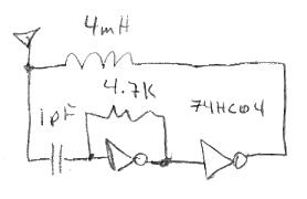
After trying to get it to oscillate with a 74HC04N this morning I'm not so sure.  It needed at least 2pF sense to keep going after I attached the antenna, and the feedback resistor needed to be raised to 4.7k, which threw off the phase.  Probed ~300Vpp at the antenna, 50ns or less phase nose (with antenna attached).  Maybe I should try for a transistor approach.  The ECL-LC oscillator is much more robust, and if I were building a processor-based digital Theremin (i.e. no FPGA) I'd go with that at this point.

"Sensing of drive through R reduces Q. What about other ways to "copy" drive current for sensing purposes?  E.e. current mirror which mirrors drive current for sensing purposes... Any ideas?"

Hmm, that's something to think about.  The most obvious method of sensing would be a tap or another winding on the low-Z drive end of the coil.  But taps aren't a free ride, any current they require tends to damp oscillation (lower Q).  And being so close to the HV end of the coil they can capacitively couple.  The thing with these oscillators is that there isn't much room for phase error, so you can't get too fancy when processing the feedback (unless you do it in an FPGA, where you can get crazy fancy).

Posted: 1/3/2021 2:43:31 AM
dewster

From: Northern NJ, USA

Joined: 2/17/2012

Transimpedance LC Oscillator (continued)

OK, played around with it a bit more on the bench (breadboard):

Removing the feedback capacitor dramatically improved the phase alignment, and therefore the tendency to oscillate, and enabled me to reduce the sense capacitor to 1pF.

Above: that's ~330Vpp at the antenna with 3.3V drive, which is consistent with decent phase alignment and the Q=100 coil.  Relatively immune to supply voltage fluctuation, though the ECL-LC differential oscillator is the champ here.  It oscillates with a 0.5mH coil, though at ~200Vpp due to the somewhat poorer phase alignment.  In both cases oscillation ceases with relatively minor hand touching of the insulated antenna (again the ECL-LC oscillator wins here) but it starts right back up after hand removal.  Seems relatively stable at delayed trigger, a bit of jumping that may be due to my rickety setup.  Current draw is ~6.25mA with the 0.5mH coil.

Since it improved with the removal of the feedback C, it might behave better with less parasitic capacitance, such as on a proper PCB.  But I have mixed feelings regarding the use of high speed multi-transistor IC's in the beating heart of an oscillator, as they tend to be twitchier and have more delay then discrete constructs.

Posted: 1/3/2021 8:00:20 PM
dewster

From: Northern NJ, USA

Joined: 2/17/2012

One Transistor Transimpedance Buffer Oscillator (Gain <1!)

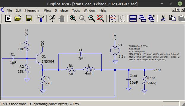
You can actually use just the voltage gain of the LC tank to sustain oscillation [LINK]:

Above is a transimpedance (RC high pass) unity gain buffer sensing the antenna swing and driving the tank.

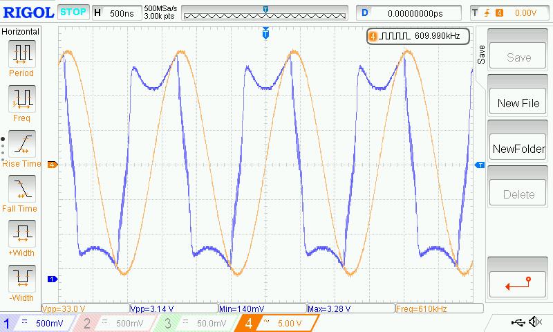
Here it is on the scope (drive waveform is a bit funky but the phase is good):

~200Vpp at the antenna, ~7mA current draw at 3.3V, EXTREMELY tolerant to VCC variation, works down to ~1V or less, seems stable.  Oscillation stops when I touch the insulated antenna, starts right back up when touch removed.

I tried a NPN/PNP buffer variant that worked like a dream in LTspice but I couldn't get it to oscillate on the bench.  One could probably also implement a constant current pulldown here instead of the 220 ohm resistor (NO!  see edit below).

[EDIT] Just tried a current mirror pulldown which simulates fine, but I couldn't get it to work no matter what I tried on the bench.  Also tried removing R2 (15k pulldown) and that increases the antenna to ~240Vpp, with a ~10mA current draw. That type of biasing is probably rather beta specific though.

[EDIT2] 33k for R2 seems to work well.

Posted: 1/4/2021 8:39:04 PM
dewster

From: Northern NJ, USA

Joined: 2/17/2012

Push-Pull Buffer

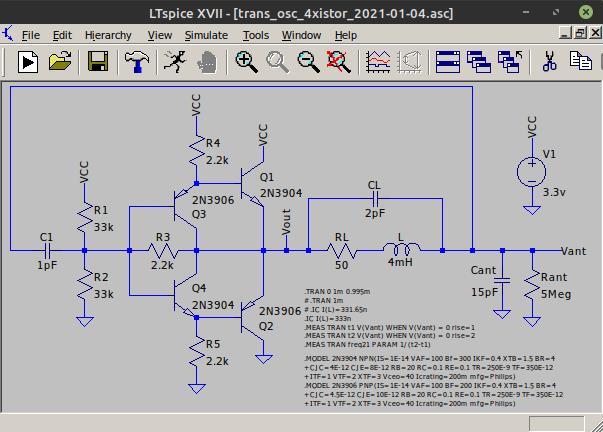
I developed a nifty 4 transistor push-pull ~unity gain buffer for use as coil drive in these latest oscillators:

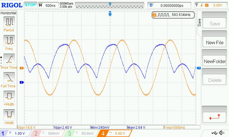
Above is a full transimpedance oscillator incorporating the new buffer.  The buffer itself consists of Q1 thru Q4, and R3 thru R5.  I just breadboarded it and it's running on the bench as we speak:

The oscillator with the new buffer draws a mere 3mA from the 3.3V supply, works down to about 2V, and is extremely stable with VCC variation.  It provides a nice centered ~2Vpp square wave to feed to logic, and a healthy 240Vpp swing at the antenna.  Stalls with a semi-hard pinch on the insulated antenna, but restarts without a hitch.

I developed the buffer in LTspice by minimizing the initial oscillation "kick" (~1.5nA in L) followed by much trial and error in terms of topology and component values, to get the oscillations to start and build up as soon as possible.  Then I looked at phase and such and adjusted things to give the best drive waveform and antenna swing.  For optimal functioning, R1 & R2 (and possibly C1) should be adjusted depending on the inductance of the coil the capacitance of the antenna, and their Q at resonance.  Here's the LTspice file: [LINK].

I really don't think I could have done this without LTspice, so hats off to Linear Technologies for providing this great tool for free!

Next up: Incorporate this new buffer in the ECL-LC 6 transistor oscillator (to make it 8)!

Posted: 1/5/2021 4:01:26 PM
dewster

From: Northern NJ, USA

Joined: 2/17/2012

8 Transistor ECL-LC Oscillator (With New Buffer)

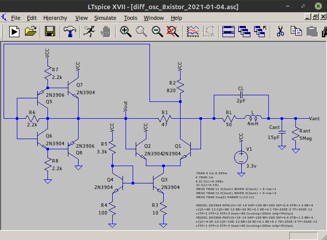
This morning I incorporated the new 4 transistor buffer (see previous post) into the ECL-LC differential oscillator [LINK]:

Above: the new push-pull buffer is on the left formed by Q5 thru Q8.  R2 can be used to fine tune the drive duty cycle; increase sense resistor R1 if oscillation isn't happening for your inductor.

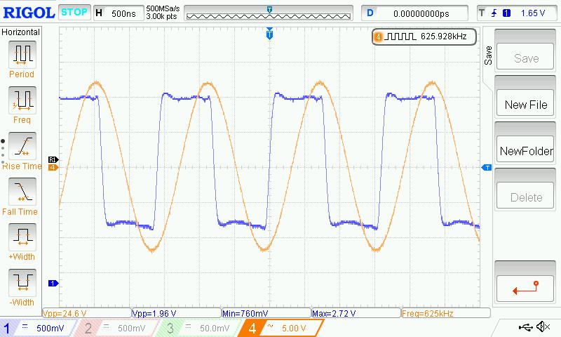
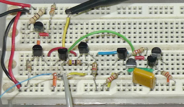
Above: the oscillator running on my breadboard.

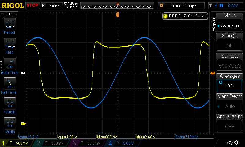
Above: the oscillator coupled with my 3.729mH / 48.5 ohm DCR air core coil and an insulated EW type rod antenna.  230Vpp at the antenna, extremely stable frequency with VCC variation, works down to 2V, draws 6.8mA @ 3.3V, nice centered square wave output to logic.  Drive phase is very good and requires no adjustment when changing coil L or antenna C.

I also tried it with coils from 10mH all the way down to 210uH and the response was a bit more ragged with the tiny inductors (probably due to lead inductance ringing, insufficient decoupling, and such).  An EW type choke required 47 ohm R1 and an attached antenna, the air cores resonated fine with 33 ohm R1 and no antenna (at SRF).  I think 47 ohms here is a good compromise between high Q, antenna swing, and guaranteed oscillation.  With the larger air cores and 47 ohms R1 I couldn't stop oscillation by grabbing the antenna with both hands.

I plan to modify the 6 transistor oscillator that I build on vector board to this 8 transistor variant, as it is clearly superior.  Vadim, give this one a try!

Posted: 1/5/2021 8:00:59 PM
Buggins

From: Porto, Portugal

Joined: 3/16/2017

Nice!
Strange different resistors in current mirror. A kind of magic?
What is drive swing? Is 1.88V on scope for 2V or 3.3V?

You must be logged in to post a reply. Please log in or register for a new account.