Linearity Meter

Posted: 11/8/2016 8:34:15 PM
dewster

From: Northern NJ, USA

Joined: 2/17/2012

Window blind hardware seems to be crying out for a project like this:

The plastic beads on a string would likely be fairly benign in terms of messing with the capacitance, and hooking a stepper motor up to it would give a lot less magnified error than the long arm approach.  And it would be inherently linear, so no compensation (other than maybe some kind of calibration) would be necessary.

The "arm" could be counter sprung so that the beaded string wouldn't have to carry any weight.  Or make the whole setup vertical rather than horizontal to avoid the droop from gravity.

Posted: 11/9/2016 6:54:07 PM
ILYA

From: Theremin Motherland

Joined: 11/13/2005

"And it would be inherently linear"

"Linear vs. angular" dispute?
Perhaps the answer depends on the playing technique. IMHO (I watched myself and some performers), the angular movement of forearm is predominant.

dewster, an interesting alternative to long gear belt!

Posted: 11/9/2016 6:59:42 PM
ILYA

From: Theremin Motherland

Joined: 11/13/2005

A bit of diagrams, which I follow to.

Some clarifications.

1. Any mechanical relay has a triggering delay + bounce interval. The new measuring cycle should be  started just after some protecting interval (say, 10 ms).

2. After every step, the rotor performs unwanted relaxed oscillations and measurement results can be destorted. An additional pause is also required here. To save the time, the "reference cycle" (i.e. measurement without antenna) being done during the relaxation interval.

3. In idle mode device gives the rest to relay. At this time two values on the LCD (which are usually  the "reference" and "main" results) are correspond to the two successive "main" results obtained with antenna connected.


The "Start-Up Pause" allows the operator to move away from the antenna before the first cycle. The high resolution (1 mm) mode is required just for the short distances (the process starts here).  On far distances the "full step" (1 cm) is quite acceptable. To accelerate measurements , the special parameter "u-step Range" is provided. It defines the step number when the "full step" mode will be turned on (value 0 lets start with a 1 cm step immediately).

And finally, I want to add a "two way" mode, which doubles the data collecting and returns the "hand"  to start position (can be disabled).

Posted: 11/10/2016 12:30:59 PM
dewster

From: Northern NJ, USA

Joined: 2/17/2012

"Linear vs. angular" dispute?  Perhaps the answer depends on the playing technique. IMHO (I watched myself and some performers), the angular movement of forearm is predominant."  - ILYA

Yes, you make a good point.  Analog Theremins have largely constant/fixed sensitivity (note spacing) across designs, which I feel is generally too cramped.  This leads to stock still poses and small precise hand movements.  So players tend to keep their upper arms glued to their bodies and pivot the forearm from there to maintain support, often doing a lot of the work with just their fingers.

My prototype isn't making noise yet (waiting on some cable clamps from Amazon) but I stand at it every now and then to "feel" the ergonomics of the setup.  We'll see I suppose, but I'm thinking of around 2 octaves for melodic playing over a hand distance delta of maybe 0.5 meters might be comfortably wide for the pitch field.  A lot of this is forearm pivoting, with assist from upper arm and hand movement.

From my capacitance simulations the forearm doesn't have a lot of input, the close hand really dominates.

"After every step, the rotor performs unwanted relaxed oscillations and measurement results can be destorted. An additional pause is also required here."

Could you somehow mechanically (or electrically) damp it?

Posted: 11/14/2016 6:06:46 PM
ILYA

From: Theremin Motherland

Joined: 11/13/2005

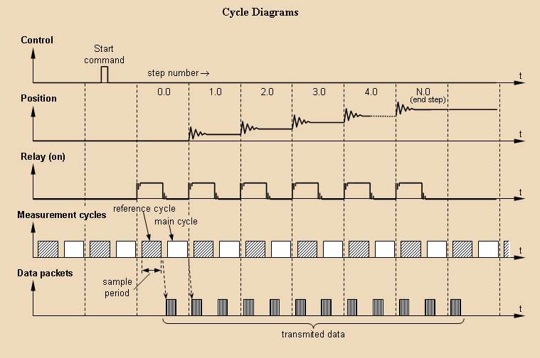
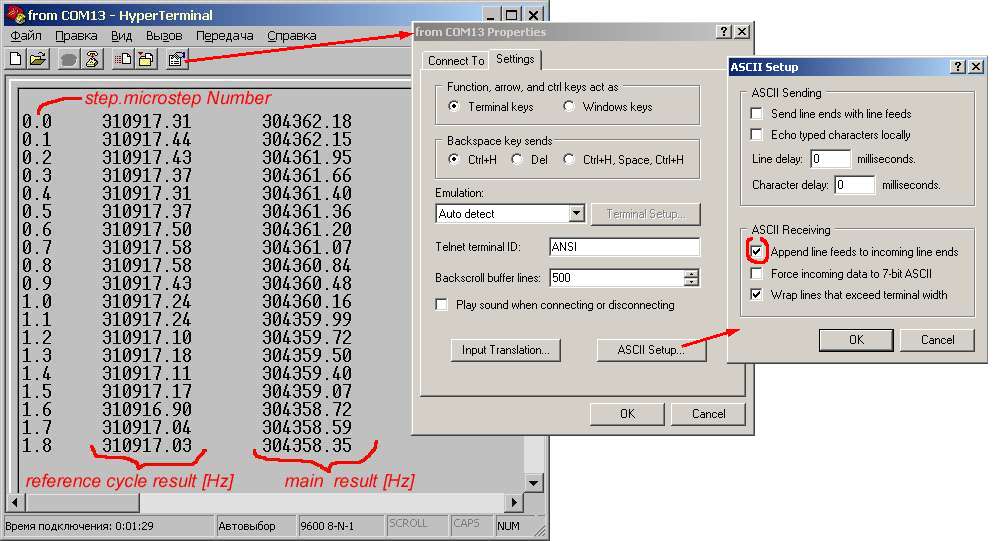
The data packet used (nothing complex, it's just a common text message): 
<step number> <"tab"> <result 1> <"tab"> <result 2> <"end of line">

So, all you need for data logging is a standard communication application (like the Windows Hyper Terminal) and to press a "Start" key.  Some extra setting can be needed for HyperTerminal:

My own application which allows remotely starting measurement, plus some service functions::

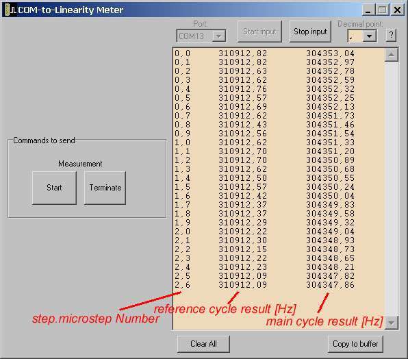
The "Start" button sends the letter "S", the "Terminate" sends "T" (control board accepts and runs these commands).
After applying the "Copy to buffer" command (even "on the fly") the data can be directly pasted into Excel cells. 

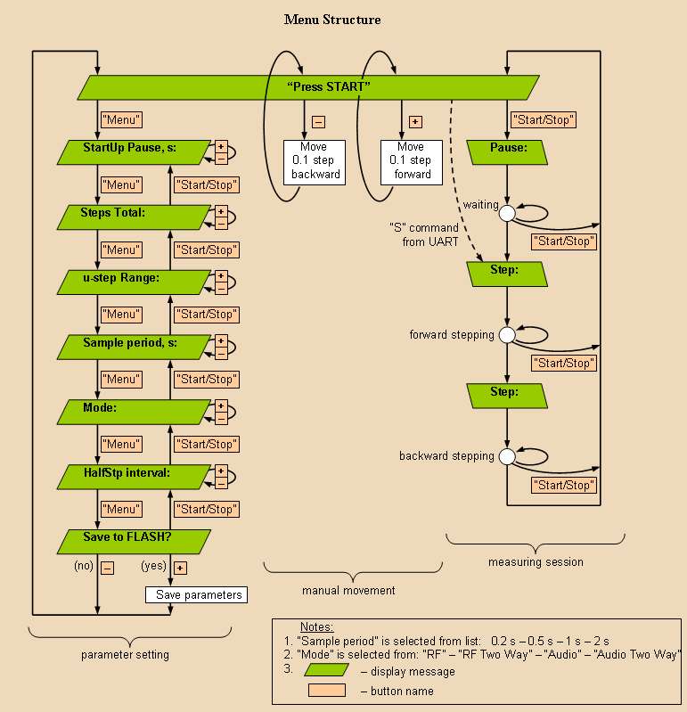
After evolutions, menu of control board looks like this: 

Could you somehow mechanically (or electrically) damp it? - dewster

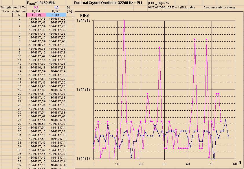
In microstep mode it is not so noticeable, but in the full step mode the amplitudes (by eye) reach a full step value and the relaxation time is about a second. Using a sample period 1 s and more (refer the Cycle Diagrams), it is possible not to worry about it. At the moment I am experimenting with the hard steel lever.  A lighter "hand", I sure, will behave differently.  "Sail effect"  plus, maybe, usage of elastic materials.

As for the preventive, the special stepping algorithm was implemented: every step (or ustep = 0.1 step) is extra half divided. Two "halves" are used for acceleration and deceleration phases. With a properly set duration ("HalfStp interval"), the rotor finishes its movement with a zero speed and unwanted oscillations do not occur.

In practice, inhomogeneities of torque do not let to oscillations be completely suppressed. Nevertheless, such the algorithm makes them much smaller, and sometimes unwanted oscillations are completely disappear.


Posted: 11/14/2016 11:10:34 PM
dewster

From: Northern NJ, USA

Joined: 2/17/2012

"At the moment I am experimenting with the hard steel lever.  A lighter "hand", I sure, will behave differently.  "Sail effect"  plus, maybe, usage of elastic materials."  - ILYA

Exactly.  Maybe try a lever made of very lightweight plastic with the paddle on the end given a single coat (on one side, no need to do both) of aluminum tape.  The reduced mass might be less prone to oscillation, allowing air resistance to damp things.

Would a small resistance in series with the motor winding help?  Or driving the motor with lower voltage / current?  I've never messed with steppers.

Posted: 11/15/2016 6:21:43 PM
ILYA

From: Theremin Motherland

Joined: 11/13/2005

Let's temporarily put aside the stepping questions.

The current implementation of frequency meter gives the 94 kHz to 12 MHz range and resolution according the formula below. Pre-calculated values for some T and f are placed in the table:

With these resolutions, I think, I can detect a sneeze in the next room. Could it be a good core for touchless synthesizers like the Theremini and Open.Theremin.UNO?

Checking the algorithm and estimated resolution.

I ran the crystal oscillator chip 1.8432 MHz instead of the RF oscillator board.

The data from the log give an idea about
1.  matching to declared frequency,
2.  actual resolution (the distance between adjacent values). That is possible thanks to the high stability of MHz crystal oscillators  and low frequency drift of the ones.

The result: 0.4 Hz vs 0.38 for 0.2 s sampling period and 0.08 Hz vs 0.077 for 1 s sampling period.  Not so dusty. A minor reduction I associate with a 32.8 bit fixed point arithmetics used.

It is interesting to check the version with an internal clock 24 MHz (32768 Hz  x 732 = 23.986176 MHz) which is derived from the watch crystal oscillator 32768 Hz, under Cypress recommendations. The data speak for itself:

To hell with it!

Posted: 11/15/2016 7:29:09 PM
DOMINIK

From: germany, kiel

Joined: 5/10/2007

Ilya - one thing: i don't get how you transfer all that to each and every theremin.

By the way i appreciate your efforts and definately like the appearance of your prototypes!

* Dominik 

Posted: 11/15/2016 9:47:26 PM
dewster

From: Northern NJ, USA

Joined: 2/17/2012

"With these resolutions, I think, I can detect a sneeze in the next room. Could it be a good core for touchless synthesizers like the Theremini and Open.Theremin.UNO?" - ILYA

One can measure just about anything as long as one is given sufficient time to do the measuring.  And this is the rub when it comes to Theremins, where you need both sufficient resolution and sufficiently quick response.  Even your shortest measuring period of T=0.2s is IMO much too long as it corresponds to a bandwidth of 5Hz (which is in the ballpark for the Theremini bandwidth, and which many consider to be fairly unplayable because of the limited bandwidth / high latency).

This is why my goal was to design the most sensitive, stable, and noise resistant oscillator I could.  High Q air core LC with precise drive / feedback, coupled to a plate antenna, followed by a 4th order low pass anti-aliasing filter, and digital comb filter for mains hum rejection.  This is all to improve the trade-off between measurement bandwidth vs. measurement precision.  Adding any bulk capacitance to the antenna that doesn't "see" the hand mutual capacitance degrades this trade-off.

I believe limited bandwidth (inertial delay) is much less trouble for a Theremin player than high latency (transport delay) but I haven't tested this hypothesis.

"It is interesting to check the version with an internal clock 24 MHz (32768 Hz  x 732 = 23.986176 MHz) which is derived from the watch crystal oscillator 32768 Hz, under Cypress recommendations. The data speak for itself:"

It's not jumping out at me what I should be discovering.  Could you speak for the data a bit? :-)

Posted: 11/16/2016 6:23:01 PM
ILYA

From: Theremin Motherland

Joined: 11/13/2005

Dominik,
for each and every investigated theremin:

1. RF osc board will be disconnected and removed.
2. Audio output of investigated theremin  will be connected to control board directly (or maybe via an extra buffer, although the PSoC internals have its own opamps which can be used instead). If the investigated theremin is a "self contained" (does not have an audio output), an extra microphone could be used.
3. The control board is set to "Audio mode", that means a 0 to 20kHz input range (still not implemented).
4. Platform with "arm" is placed close to theremin antenna (to keep the 32 cm distance). The cables and netbook are far away.
5. Option: a Piter Pringle body simulator can be placed behind set.
6. Push "Start" and enjoy.

"Could you speak for the data a bit?" - dewster

At the moment just my eyes can speak -). And they are talking about increased dispersion. I don't know how calculate it numerically (for the first case the dispersion is under the resolution, definitely, plus a systematic factor - the slow drift).


You must be logged in to post a reply. Please log in or register for a new account.