D-trigger as heterodine mixer: aliasing

Posted: 4/14/2017 4:05:44 AM
Buggins

From: Porto, Portugal

Joined: 3/16/2017

Any reason you're going for this high of an operating frequency?  Granted, this is in a pretty quiet spot in terms of other terrestrial transmitters.  Lower frequencies require larger inductors, but they are easier to drive from a phase error standpoint, and are easier to measure.  Though you could just use a digital divider (like you are doing).

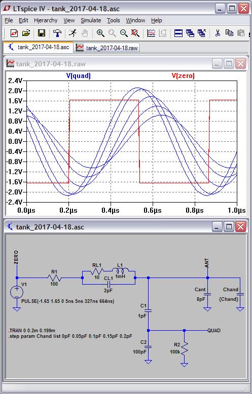
High working frequency is caused by inductor 560uH and antenna capacitance (8-9pF) - if the goal is to maximize (Fmax - Fmin)/Fmax value I cannot apply caps in parallel with antenna.

Inductor size is limited by cabinet dimensions. Height is 4cm so max coil diameter is limited by ~35mm.

Max coil length is 10-12cm. Winding length 12cm with 32mm diameter would give me 1mH - max inductance I can fit in this cabinet. It has 2.6MHz self resonance and 1.8pF self capacitance.


UPDATE:

Tested on MCU.

Histogram of measures (signal period measured in 1/60,000,000 second intervals):

Interval stats
interv    count
24033    15
24034    155
24035    430
24036    543
24037    456
24038    322
24039    201
24040    215
24041    158
24042    14
Best: 24036    543

Stability is good enough (but may be better). I'm expecting narrower peak +-1 measure.


Sad news. Sensitivity is very bad. When hand is 50cm from antenna, difference in measure by 1 caused by hand movement ~1cm.

Only close to antenna movement gives meaningful changes in signal.

Probably, need to improve oscillator...

Maybe, such a bad sensitivity is caused by antenna laying on wooden table?


Posted: 4/14/2017 2:31:34 PM
dewster

From: Northern NJ, USA

Joined: 2/17/2012

"Inductor size is limited by cabinet dimensions."  - Vadim

IMO it's a big mistake to have the cabinet dictating the components too early in the design cycle.  Form should follow function, not the other way around.

You should also experiment with smaller diameter wire for your coils.  The lower calculated Q due to the higher resistance isn't nearly as important as it seems.  With higher frequencies the skin effect starts kicking in, which effectively gives you a smaller diameter wire anyway.  And radiation losses limit top Q.  Just about any single layer air-core coil will work.  I find those that have roughly equal dimensions (height ~= diameter) use the least wire, are relatively compact, and perform well.

"Only close to antenna movement gives meaningful changes in signal.

Probably, need to improve oscillator...

Maybe, such a bad sensitivity is caused by antenna laying on wooden table?"

You need lots of real-world, low-noise resolution to go this route, which makes it a rather difficult road to travel.  But yes, you need to mount that antenna on a piece of plastic.  And a plate antenna will give you more sensitivity as well.

The bobble in your numbers could easily be AC mains pickup.  Try measuring over some multiple of your AC mains period (1/50Hz?).

==========

I'm playing around with your recent oscillator in LTSpice.  Try this:

- Remove C3 and C4 (replace with wires).

- Remove R1.

- Change R3 to 470k.

- Change C1 and C2 to 220pF.

Posted: 4/18/2017 6:29:50 AM
Buggins

From: Porto, Portugal

Joined: 3/16/2017

I'm playing around with your recent oscillator in LTSpice.  Try this:

- Remove C3 and C4 (replace with wires).

- Remove R1.

- Change R3 to 470k.

- Change C1 and C2 to 220pF.


Tried. It produces very strange waveform.

I've changed my plans a bit. Now I think that direct measure of frequency cannot get enough sensitivity / precision.

Some kind of heterodyning is required to extend relative frequency change range (2..3% of pitch change expected for direct measure reduces sensitivity too much).

Even D-trigger will be better. I've checked how it works once again and now I see that it's aliasing distribution has sqrt() dependency on frequency diff between fixed and variable pitch. So, for far hand distance (smaller diff between fixed and variable pitch), aliasing points are closer, and for near hand distance aliasing is bigger, but it's not a big problem. So D-trigger seems like not as bad as I thought before.

XOR mixer and all ADD (mix+AM detect) seems to have the same problems with aliasing as D trigger.

So, working solution could be analog multiplier as mixer - it should not have any aliasing. Now I'm playing with LTSpice trying to get good sine waves from variable pitch oscillator (your idea to get better sine wave from tank seems useful).

Signal on Q3 collector looks like expected analog multiplier output


Posted: 4/18/2017 2:38:23 PM
Buggins

From: Porto, Portugal

Joined: 3/16/2017

Playing with analog multiplier mixer model in LTSpice.

Working good in LTSpice.


Posted: 4/18/2017 5:37:25 PM
dewster

From: Northern NJ, USA

Joined: 2/17/2012

Vadim, I want to give you a quick view of the upside down approach:

Link

Drive is a fixed frequency square wave.  As you can see, even with a Q killing 100 ohm series drive, the phase and amplitude response to a change of only 0.2pF is quite profound.  This is a trivial but very impressive demonstration to do on the bench if you have a 2 channel scope, a function generator, and a decent coil.  Phase gain is Q/pi, which can be pretty high in a single layer air-core solenoid.  It might actually be necessary to kill the Q somewhat in order to accommodate the full playing range of the hand.

Posted: 4/18/2017 5:47:20 PM
Buggins

From: Porto, Portugal

Joined: 3/16/2017

Drive is a fixed frequency square wave.  As you can see, even with a Q killing 100 ohm series drive, the phase and amplitude response to a change of only 0.2pF is quite profound.  This is a trivial but very impressive demonstration to do on the bench if you have a 2 channel scope, a function generator, and a decent coil.  Phase gain is Q/pi, which can be pretty high in a single layer air-core solenoid.  It might actually be necessary to kill the Q somewhat in order to accommodate the full playing range of the hand.


Thank you for sharing your schematic.


I've played with similar model (reinvented by your description earlier in this thread).

2MHz Xtal output feed to LC with resonance near to 2MHz.

Found that it's hard to detect phase shift. Probably, amplitude change would be monitored more easy.

Results:

Output is DC voltage - may be measured with MCU DAC. Gives up to 16 bit of data.

I did not check it on breadboard.

Not sure if implemented AM demodulator properly. Amplitude on antenna varies from 90V to 40V.

Do you think it makes sense to try this approach?

Do you know some good AM demodulator schematic? (better than my one)


At 2MHz it's hard to use XOR phase detector. I believe, precision will be too bad.

But if working frequency is lower, probably XOR + LP filter could give usable output.


UPD: Tuned analog multiplier part values a bit - got 2V output from multiplier.

Posted: 4/18/2017 7:33:42 PM
dewster

From: Northern NJ, USA

Joined: 2/17/2012

"At 2MHz it's hard to use XOR phase detector. I believe, precision will be too bad." - Vadim

Depends on the logic family, or indeed if you even do it in jellybean logic.  I would do true digital phase detection because AM detection could be prone to picking up RF, mains hum, and other environmental noise.

Resolution in the FPGA I'm using would be ~400MHz or 2.5ns with DDR I/O.  I would dither the drive by at least this value to increase resolution and eliminate dead spots.  (Then again, with an FPGA I wouldn't choose this route.)

I've quickly set up this simple experiment many, many times in the past.  It's a great way to get a feel for LC resonance, Q multiplication of I/O phase, Q multiplication of voltage, as well as environmental noise levels and what you might expect in terms of numbers from the analog process, relative gains and intrinsic C of various antenna geometries, etc.  I can't recommend the exercise highly enough, set it up and play around with it for a week or two, and you will have a much better grasp of Theremins in general.  Then move on to oscillators.

Posted: 4/19/2017 3:41:30 AM
Buggins

From: Porto, Portugal

Joined: 3/16/2017

"Depends on the logic family, or indeed if you even do it in jellybean logic.  I would do true digital phase detection because AM detection could be prone to picking up RF, mains hum, and other environmental noise.

Resolution in the FPGA I'm using would be ~400MHz or 2.5ns with DDR I/O.  I would dither the drive by at least this value to increase resolution and eliminate dead spots.  (Then again, with an FPGA I wouldn't choose this route.)

I've quickly set up this simple experiment many, many times in the past.  It's a great way to get a feel for LC resonance, Q multiplication of I/O phase, Q multiplication of voltage, as well as environmental noise levels and what you might expect in terms of numbers from the analog process, relative gains and intrinsic C of various antenna geometries, etc.  I can't recommend the exercise highly enough, set it up and play around with it for a week or two, and you will have a much better grasp of Theremins in general.  Then move on to oscillators."

It looks too simple solution :)

Where are the traps? Why everyone is using oscillators?


Let me try this approach. Phase shift to voltage convertion seems to be most simple solution (XOR -> LP filter -> ADC).


Posted: 4/19/2017 3:59:14 AM
dewster

From: Northern NJ, USA

Joined: 2/17/2012

 "Where are the traps? Why everyone is using oscillators?"

I haven't analyzed it for linearity.  It could be that the response isn't practical for the pitch side?  People just like analog oscillators heterodyning (that's not a real Theremin!)? Who knows.  But it's highly similar to Theremin volume circuits that uses an EQ coil and AM detection.  Worth looking into I think for a processor-based digital approach (if you have precision PWM and A/D) as it gives a huge signal for very little delta C.  A lower Q coil / resistive drive might actually be an asset, so the coil could be wound with finer wire and be substantially smaller.  But maybe there's a trap lurking.

I think there is a strong tendency in this field for designers to pick one way to do things and stick with it come hell or high water, which is human nature I suppose.  Lots of looking back at retro solutions, to the point where tubes are still seriously advocated.  Not saying everyone else is wrong, and going your own way can be a lot of work in terms of new research, failures, and such.

Posted: 4/20/2017 8:20:20 AM
Buggins

From: Porto, Portugal

Joined: 3/16/2017

dewster,

I'm playing with phase shift based sensor model in LTSpice. Results look nice so far.

Green lines - PWM signal based on phase shift. Blue lines - lowpass filter output for MCU ADC.

Hand capacity range is 0..3pF with 0.1pF step.

I believe 16bit ADC may catch enough information for further processing.


What is typical environment influence (when device is moved to another environment; assuming no big metal objects nearby in all cases)? Is it possible to avoid tuning (e.g. by changing of reference frequency)? Is it less than 1pF?

What caps are you using? All my caps have 50V working range. Could there be any problems if higher voltage is applied? Antenna voltage can easy exceed 300-500V amplitude according to LTSpice model.


You must be logged in to post a reply. Please log in or register for a new account.