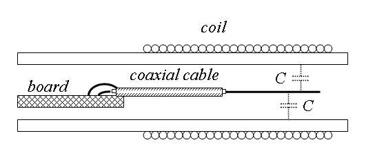
I'm not as good at MSWord as you ILYA, so here's a sketch:

There is an impedance gradient along the coil, with the drive end being low Z and the antenna end being high Z. When it's oscillating you can run your finger over the windings, and touching those closest to the drive end will give lowest "heterodyned" pitch, those closest to the antenna end will give the highest pitch. (I was trying to get FredM to look into this as an alternative to the variable C rods he was working on as a controller input.)
So if the 1pF sense capacitor wired axially thorough the coil was distributed in space (left drawing), it too would have an impedance gradient similar to that of the coil, and therefore would likely interact with it less, but that is impractical. So instead of a continuous distribution we could use a lumped distribution, say five 4.7pF in series (right drawing). This would help with ESD too, as it would multiply the capacitor working voltage by 5.
The idea is to make it so the coil sense wire "sees" as little stray C as possible, as absolute sensitivity is vital to this sort of digital Theremin. Though I'm not saying the lumped C arrangement is mandatory, just that it is more ideal than a single C.


