


"That’s the theory. In practice, you can’t predict what will exactly happen with a single ESD." - Thierry
Clamping at a relatively high voltage point in a resonant LC circuit might actually make things worse. The sharp edge has tons of harmonics.
"That’s the theory. In practice, you can’t predict what will exactly happen with a single ESD." - Thierry
Clamping at a relatively high voltage point in a resonant LC circuit might actually make things worse. The sharp edge has tons of harmonics.
In the tVox tour, the RF signals aren’t clamped, the clipping level is above the signal’s Vp, leaving some headroom, so that only stuff with higher voltage than expected is clamped. I thought, I’d written that by mentioning the signal levels at the points where the surge arresters are inserted.
RC on drive side is obviously frequency dependent, so you would have to tailor it to the oscillation frequency (i.e. the value of your coil and antenna and environment, which is why it's rather problematic).
In simulation, when tuning input R and checking Antenna swing, I see that R should be chosen to keep input voltage on inverter big enough (~80% of Vcc) but not too big (when clamping diodes on 2g04 and ESD protection start working). In other schematics, good oscillation can be obtained with clamped input.
It looks like keeping input in linear range is required to have proper phase shift on input.
On simulation, bigger L (1-2mH) gives better antenna swing.
Not sure if ltspice model is close enough to real hardware. I've added diodes + 1pF as ESD IC simulation, and just hope that 2G04 input capacity is included into its spice model. I hope, wires on PCB don't add big C.
Besides RC phase shift on input, there is additional const phase shift - delay of inverter.
Having RC + inverter delays which depend on environment looks as a big problem for precise sensor.
But looking at antenna voltage swing showing high resonance, I would expect good performance from this sensor.
Colpitts oscillator on NPN gives 2-3 times smaller voltage swing.
[color=#008e02]"It's not a good behavior for theremin. Trying to figure out how to keep oscillator working while touch."[/color]
Insulate it? Helps with ESD too. They all poop out to some degree.
You might want to lift the coil up off the wood a bit, it's probably experiencing significant C. You antenna is connected to the wood? If so, you're losing some absolute sensitivity there too. I wish wood was more like plastic in terms of C, it's not the most ideal thing to build Theremin cabinetry out of.
I have some ideas how to fix oscillation while touching.
I'll try to reduce R on inverter input from 2Meg to 1Meg and/or add centering divider on inverter input.
BTW, how do I simulate hand touch in LTSpice? R from antenna to ground? R and C in parrallel to ground?
I would keep antennas non insulated - as on EW.
I've added ESD protection IC with small, 1pF input capacity. Max voltage is close to SP721.
Plywood cabinet I'm using for testing was built for another, fpga based, design.
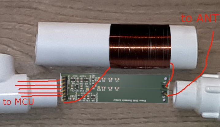
For teensy theremin, I'm going to use pipe monster for antenna mount and oscillators (with L winding right on 40mm tube and oscillator placed inside tube).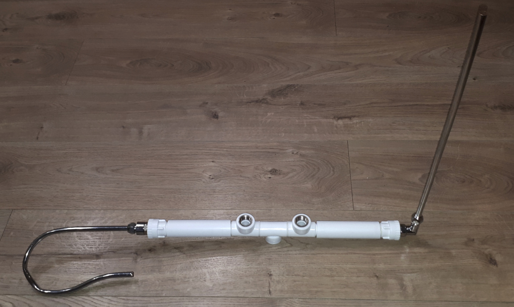
Small plastic cabinet (3d printed?) for PCB will be mounted to tubes in center.
Dewster: "To know anything about ESD you have to test to failure, and I don't know of any Theremin designers do that."
I did. The shocker was a piezo igniter from a lighter. To be honest i just let three 2N5484 pass into electric heaven (with just one click each). With a Bourns 20xx-09 the FETs survived and since then Gas Discharge Tubes are parts of a subscope. I also tried the 70V version but some of those were lighting up steadily too early and causing sparkling sound  .
.
"Besides RC phase shift on input, there is additional const phase shift - delay of inverter." - Buggins
I was thinking the input RC is how it was functioning. All oscillators that aren't phase locked will have some sort of delay through the active component.
"Having RC + inverter delays which depend on environment looks as a big problem for precise sensor."
Maybe, maybe not. See if it drifts a lot.
"I've added ESD protection IC with small, 1pF input capacity. Max voltage is close to SP721."
What IC is that? [EDIT] Oh, I see from the silkscreen it's IP4220CZ6. That has low capacitance!
"I did ... Gas Discharge Tubes are parts of a subscope." - DOMINIK
That's great! I wasn't saying I knew no designers tested for ESD, just that I wasn't aware of it (but now I am!). Thank you both for setting me straight.
Vadim, for possibly better ESD protection, use a small resistor between the CMOS pin and the protector. That way the protector absorbs most of the ESD current, protecting the built-in CMOS ESD diodes. In your schematic you might move ESD2 to the intersection of L1 and R1. And you might add 100 ohms or so between ESD1 and the CMOS input? Just a suggestion.
I've resolved issue with oscillation when hand touches antenna.
R on inverter input reduced from 2Meg to 1Meg. Used bigger L for testing.
Now for hand far from antenna F = 750KHz, near antenna but no touch F=710KHz
When hand touches antenna, F drops downto 250-350KHz
Received ordered Teensy4.1 and PSRAM chips.
Going to solder and test 16MB psram configuration.
Spent two days trying to debug strange behavior of DMA which should read captured timer counter for signal raising and falling edges and write to circular buffer.
Data either saved buffer once, but didn't update further, or if I tried to write some items to check if they will be overwritten by dma - got even stranger result - part of data looks like captured values, while the rest is either initial values I wrote to init buffer or value i've written.
Tried a lot of variants for DMA initialization.
Finally found root cause. It was a data cache of CPU.
Once I've added invalidation of cache region, issue disappeared.
I had similar bug while writing LCD controller for FPGA - image appeared corrupted unless I figured out that I have to flush cache for framebuffer region.
Now I have working component which is continously writing edge positions of signal to buffer.
Next step: implement moving average + IIR filter. Collect sample data to evaluate oscillator stability and noise level of sensor.
You must be logged in to post a reply. Please log in or register for a new account.


