


pitts8rh, thank you!
Very simple method!
Teensy 4.0 600MHz ARM Cortex M-7 MCU - ideal for digital MCU based theremin?
Posted: 12/9/2020 8:22:25 PM

"Oscillators are working. Sensitivity is good. Oscillation is unstable with 22 Ohm R_sense, with small (pitch) inductor. Works much better with bigger R_sense." - Buggins
What are you getting in terms of antenna voltage swing?
"Problem: on antenna touch, oscillator goes to high frequency oscillation (3-10MHz) often not recovered after removing of hand.
Tried to change R_sense to 100, 220, 1000 Ohm - no effect."
Oh, sorry to hear that. But that's not entirely surprising, there's a lot of raw HF gain coupled to a strong driver there, and all in a tiny package so the I/O are very close. I think these sorts of oscillators work best when there is just a little more gain than you need, and a weakish driver.
"Dewster, does your bipolar differential schematic work ok when antenna is touched?"
It poops out when you touch the bare metal, but not when you touch painted metal, and it pops right back to the right frequency. If the drive phase were better the voltage swing would be better (it's really hard to get good drive phase with an analog oscillator).
[EDIT] The bipolar oscillator is pretty stable in terms of supply voltage variation. I'm not using a regulator on the breadboard, and when I turn off the bench supply and it's bleeding down, the frequency doesn't change much until the voltage drops significantly.
Posted: 12/10/2020 12:46:56 PM
Vadim, have you tried adding some metal to your antennas to increase the intrinsic C? That might make the oscillators more stable / more prone to popping back to the right frequency. Try a square of aluminum foil and see if the behavior improves.
Posted: 12/10/2020 5:50:51 PM
Vadim, have you tried adding some metal to your antennas to increase the intrinsic C? That might make the oscillators more stable / more prone to popping back to the right frequency. Try a square of aluminum foil and see if the behavior improves. -- dewster
Not sure if I understood correctly. Attach foil squares to antenna rod?
I've tried to increase C - by soldering caps from antenna to ground (10pF x 4 in series = 2.5pF). I see reduced sensitivity, but not sure if there is more stability.
Going to try adding cap between pos and neg outputs of comparator. Could it prevent oscillation?
I think these sorts of oscillators work best when there is just a little more gain than you need, and a weakish driver. -- dewster
Most smooth and weak drive could be sine wave, but it's hard to implement limiter for it.
Tried fast differential amplifier based schematics, but all I managed to achieve - sine clamped from top and bottom.
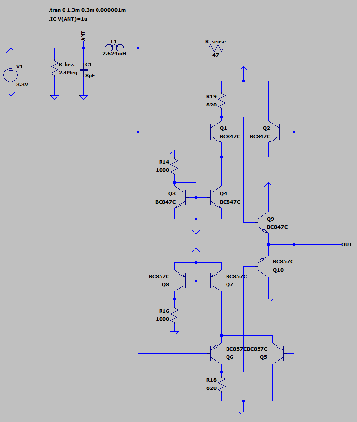
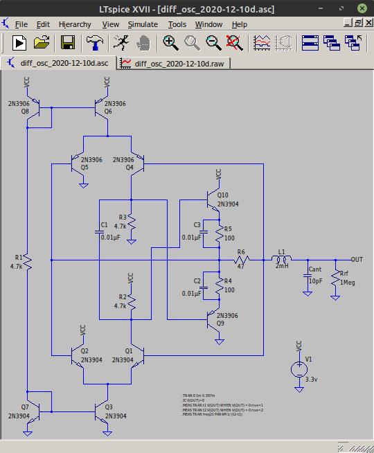
Trying to design symmetrical BJT current sensing oscillator.
It's cheaper than fast differential amplifier ICs and comparators.
Symmetry is beautiful, so such device should have better performance 
Took two differential cascades - NPN for sensing near Vcc, and PNP for sensing near GND.
Then both signals are mixed to form output.
Is there some better solution to give 0..3.3V output?
Posted: 12/10/2020 7:15:27 PM
"Symmetry is beautiful, so such device should have better performance" - Buggins
That is quite pretty! And it simulates nice!
But I think there is a potential problem with Q9 and Q10 burning themselves up at power-up? Before oscillation can start, R18 and R19 might turn both transistors on simultaneously, releasing their magic smoke?
It's probably safer to come up with a driver that utilizes a single differential pair, rather than two operating independently. I wonder if a CMOS inverter could be used here?
Posted: 12/10/2020 8:25:36 PM
That is quite pretty! And it simulates nice!But I think there is a potential problem with Q9 and Q10 burning themselves up at power-up? Before oscillation can start, R18 and R19 might turn both transistors on simultaneously, releasing their magic smoke?
It's probably safer to come up with a driver that utilizes a single differential pair, rather than two operating independently. I wonder if a CMOS inverter could be used here?
Good point about magic smoke.
Played a bit more with this schematic (new model link)
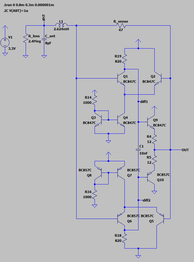
Added 10nF between output cascade bases.
Added 12 Ohm anti-smoke resistors at output cascade emitters.
Max current through them is now limited to 140mA
Outputs of two differential cascades and output cascade:
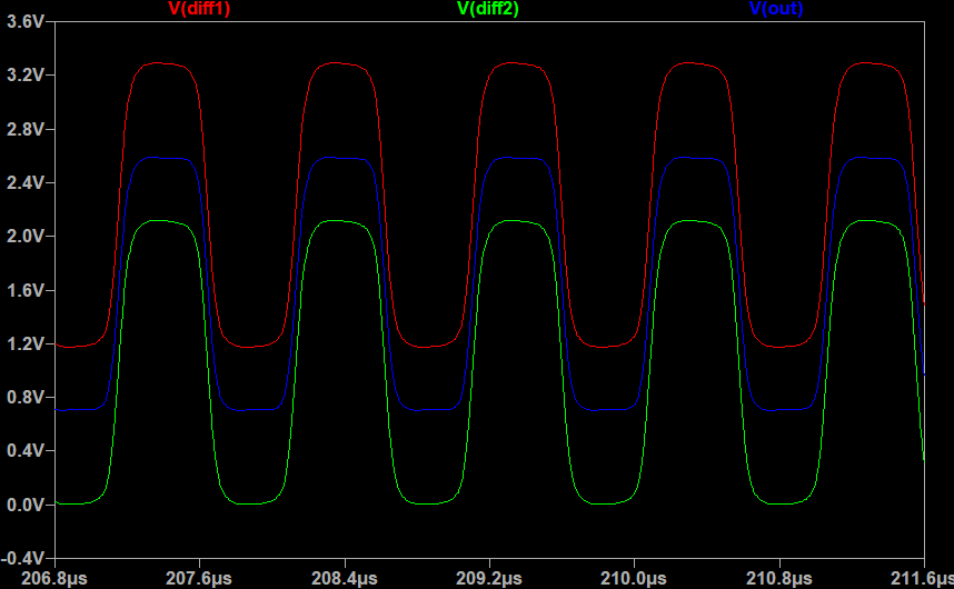
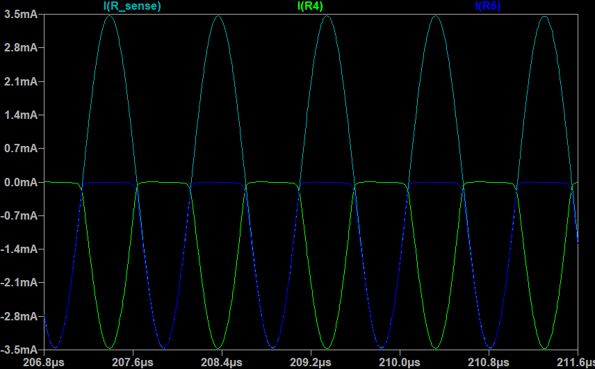
Current through output cascade emitters and through R_sense looks pretty good:
Each transistor drives only its own half of signal period.
Drive (output) signal harmonic level: 3rd harmonic is -10dB from main signal.
R_sense current is pretty clean +-3.5mA sine wave: 3rd harmonic is -50dB!
Unlike square drive, there are no peaks on crossing zero in drive current.
I believe adding of inverter as drive amplifier is bad idea not only die to introduced delay (phase shift),
but as well because square drive gives narrow peaks in drive current.
Smaller antenna swing due to non rail-to-rail drive is probably not a problem. Expected 140Vpp from 3.3V looks good enough.
Posted: 12/10/2020 11:50:05 PM
"Added 10nF between output cascade bases." - Buggins
Interesting!
"Added 12 Ohm anti-smoke resistors at output cascade emitters. Max current through them is now limited to 140mA"
If you stick a C across them you can likely use a safer, larger resistance value:
I couldn't get anything much higher than 70Vpp with 2N3904/2N3906 in simulation. Haven't benched this at all!
But I gotta say, the 6 transistor all NPN version that's been running on my bench for a while now is working pretty good, even with a traditional 10mm tube antenna. It appears to be generally stable via delayed trigger even without a voltage regulator (though I always recommend the use of one), it pops right back after stalling, and the frequency hardly varies with voltage. I honestly think it's good enough for a digital Theremin. I believe FredM determined you only need about 40Vpp or so to overcome most environmental interference - more is always better (unless you are trying to meet FCC emissions compliance!) but much beyond that is probably diminishing returns.
Can I please buy you a breadboard? ;-)
Posted: 12/11/2020 6:54:40 AM
70Vpp - with R_loss = 1Meg, 120Vpp with 2Meg, 140Vpp with 2.4Meg
Reusing the same R for both current mirrors is nice idea.
Caps in parallel with output stage resistors virtually eliminate these resistors?
Looks like drive current is getting cleaner with your changes: -70dB for biggest harmonic instead of -50dB
Output is ok for digital theremin (or some buffer can be added).
For analog theremin or FPGA theremin with ADC on input, we can produce clean sine signal using yet another sensing differential amplifier - which will have limited gain to avoid clipping.
Since drive signal is in 0.7..Vcc-0.7, we can use some cheap slower non-rail-to-rail opamp or differential amplifier.

You must be logged in to post a reply. Please log in or register for a new account.