Fascinating circuits Vadim!
"Delay is introduced in mixer/limiter/current to voltage stage." - Buggins
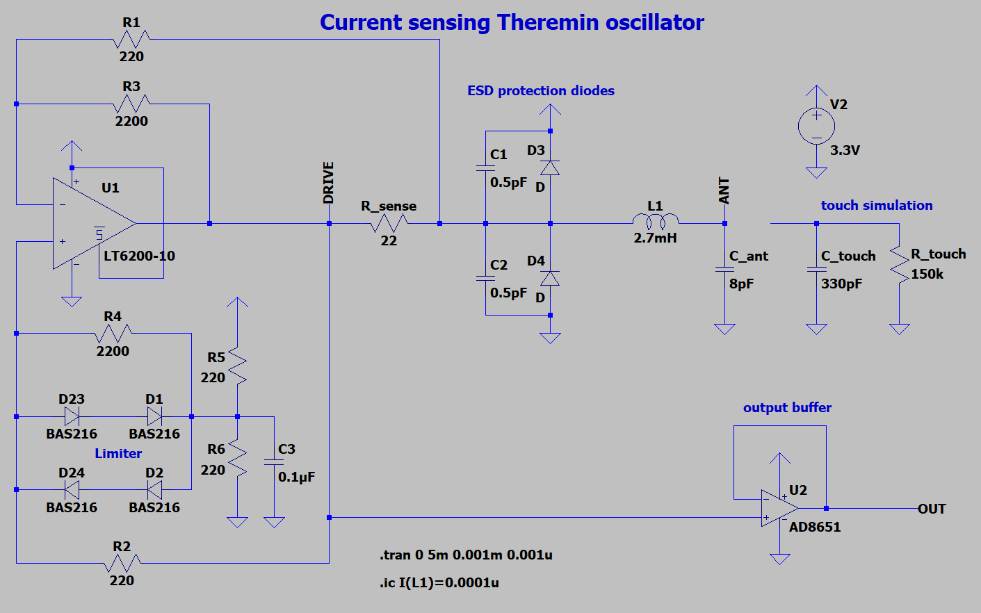
The diodes and 1 Ohm Rs seem problematic. There to prevent current starving / open loop operation? Probably a lot of added C, and a scary over voltage situation.
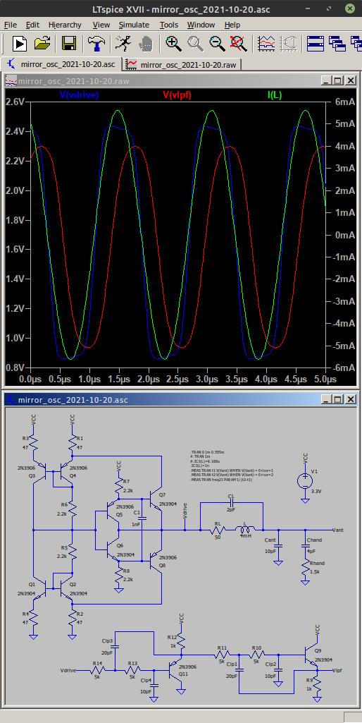
"As well, I'm trying to use two current mirrors - to provide drive signal close to supply voltage. I think it's a nice idea to implement oscillator with two pairs of current mirrors. Although, I have some troubles when trying to get it oscillating..."
Splitting the sense resistor is quite an interesting idea. If the supply voltage were higher one could maybe do cascode to speed it up a little.
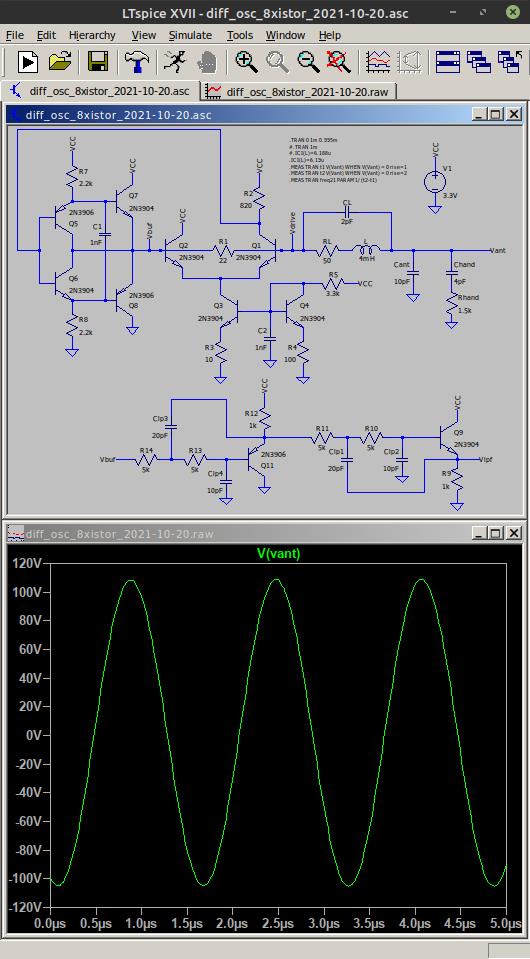
Start-up usually seems to come down to the issue of supplying some drive at crossover, the same sort of thing they run into with audio amplifiers and distortion. My 8 xistor oscillator has many elements of an audio amplifier (differential input stage, push-pull output stage) which I guess isn't a surprise.