Dewster -
Thanks to your clever CMOS oscillator design ( the last one where you effectively created a differential amplifier using two unbuffered inverters) I have been exploring CMOS in linear mode.. Its one of these topics I left behind many years ago when good quality opamps became available at reasonable prices - as a hobbyist did all sorts of stuff with CMOS - but sort of threw the baby out when I started "real" design.
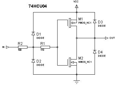
I managed to find a SPICE file for the PMOS and NMOS transistors used in the 74HCU04, and created a working model which behaves exactly as all the app notes describe - and have been playing with simulations using these parts..
Some things I have found: (using 5V supply)
1.) Amplifier - With 1V P-P input, the behaviour is quite linear, and there is not much distortion.
2.) Overdriving the input gives a soft-clipping response - I have been playing with simulations using these amplifiers as HF amps (>100kHz <1MHz) to buffer theremin oscillators..
3.) CRAZY IDEA - Drove a seperate 74HCU04 with its VCC biased with a resistor from a variable DC supply, and AC coupled a signal into VCC.. Started out by sticking REF oscillator into VCC and Var Oscillator into an amplifier constructed from one inverter.. And yes, it formed a really interesting mixer - by altering the VCC supply (bias) voltage and AC (Oscillator) levels all manner of interesting mixed waveforms (difference frequency) can be obtained - and some of these have great similarity to what Ive seen from a certain famous tube heterodyning stage!
(I even drove one oscillator into the VCC terminal and one into the "GND" terminal, with appropriate biasing etc, and that worked a treat! - simply strap a 100k resistor across an inverter, and the output of that inverter is sum mudulated by difference ;-)
(should just say that I strapped a 4.7V Zener across the supply pins, as the AC coupled signal on the supply could cause this to exceed 6V otherwise)
4.) I then messed with coupling the same signal both to the supply and the amplifier input - and yes, with some biasings / gains I did get distorted frequency multiplication - but the interesting thing was how much I was able to vary the waveform depending on biasings and gains..
5.) I am now at the stage where I have 4 HCU04's (as in, 4 complete hex inverter packages) - the first driven from fixed (normal) supply acting to buffer the osc signals, and as a filter / output buffer for the heterodyned difference (audio) output - then one U04 as a multiplier / distorter for each of the oscillators, then these drive one which is the mixer, and the output from the mixer goes back to the first for filtering etc..
..... And I have spent the last 4 hours "building" this stupid circuit, thinking "why the hell am I doing this - I would never risk putting it into production! "
Truly crazy!
;-)
http://www.qsl.net/l/lu7did/docs/QRPp/TTL_74HC04%20As%20Linear%20Amplifier_SPRATCD.pdf
SPICE PARAMETERS FOR MOSFETS:
************************************************
* NOMINAL N-Channel Transistor *
* UCB-3 Parameter Set *
* HIGH-SPEED CMOS Logic Family *
* 10-Jan.-1995 *
************************************************
.Model MHCNEN NMOS
+LEVEL = 3
+KP = 45.3E-6
+VTO = 0.72
+TOX = 51.5E-9
+NSUB = 2.8E15
+GAMMA = 0.94
+PHI = 0.65
+VMAX = 150E3
+RS = 40
+RD = 40
+XJ = 0.11E-6
+LD = 0.52E-6
+DELTA = 0.315
+THETA = 0.054
+ETA = 0.025
+KAPPA = 0.0
+WD = 0.0
***********************************************
* NOMINAL P-Channel transistor *
* UCB-3 Parameter Set *
* HIGH-SPEED CMOS Logic Family *
* 10-Jan.-1995 *
***********************************************
.Model MHCPEN PMOS
+LEVEL = 3
+KP = 22.1E-6
+VTO = -0.71
+TOX = 51.5E-9
+NSUB = 3.3E16
+GAMMA = 0.92
+PHI = 0.65
+VMAX = 970E3
+RS = 80
+RD = 80
+XJ = 0.63E-6
+LD = 0.23E-6
+DELTA = 2.24
+THETA = 0.108
+ETA = 0.322
+KAPPA = 0.0
+WD = 0.0
MY 74HCU04 MODEL:


