Measuring Antenna Capacitance

Posted: 1/1/2017 3:48:07 AM
dewster

From: Northern NJ, USA

Joined: 2/17/2012

"Have tried to approximate the dependences by analytic functions,  in all the distance range, but without success."  - ILYA

Ya, I've spent more time looking into C analytics than I care to admit.  The solutions they show you in school textbooks have tons of symmetry (concentric spheres, infinitely long coaxial conductors, etc.).  I'm certainly not the best at math, but it seems even those who are the best can't do this stuff without FEA simulation guiding them to the right expressions, even for what seems doable like parallel circular plates.  I think much of the complexity has to do with the charges on a conductor being free to move around.  Papers will come up with a near case and a far case, and often a surprisingly good fit is just adding them.  And then there's the question of mututal vs. intrinsic vs. total seen by the antenna, what are they really solving for?  (Ask a group of physicists to calculate the capacitance of the Earth and you'll get many different answers, all of them adamantly defended by their proponents.)  Simulation, backed up by real measurements such as you and I have done, are the only things I care about at this point.

Posted: 6/17/2017 9:51:26 AM
feliperodrigosek

Joined: 4/27/2017

WOW! awesome results here.

I am doing a similar experiment, and I am really struggling on calculating the static capacitance. I have seen a lot of charts and results, but I don't know how to get the capacitance.


Thanks ;)

Posted: 6/17/2017 10:07:17 AM
feliperodrigosek

Joined: 4/27/2017

I am avino trouble calculating the mutual capacitance. 

Please help


Thanks

Posted: 10/20/2017 12:01:49 AM
dewster

From: Northern NJ, USA

Joined: 2/17/2012

Human Body Model

ILYA, I'm curious.  I assume you're simply grounding the "hand" in your experiments?  This is what I'm doing in my simulations, but my real data uses my real hand (my body in a chair, on a rug, other hand holding plastic cased but grounded frequency counter).  What about the body resistance?  Using a DMM between my moistened hand and foot I measure somewhere around 1M Ohm (very approximately!).  Shouldn't the test setup take this into account?  And how about the intrinsic C of the body?  Seems like an accurate simulation should be modeling these distributed capacitances and resistances.

I bring this up because I believe the resistance is easily seen in any Theremin setup, though it's quite obvious in an oscillator that (1) doesn't have an EQ coil and (2) that accurately tracks phase (no phase error, like my digital Theremin oscillator).  I say (1) because EQ coils do a sort of offset resonance that normally affects amplitude, and (2) because even small phase error can cause a quite large amplitude change in high Q resonance.  

As my hand approaches the antenna the oscillation amplitude goes way down.  If my body were just C to ground this couldn't happen, clearly my body R is damping the oscillator Q.  I'm wondering what effect this has on the oscillator frequency.

Posted: 10/22/2017 12:15:02 PM
ILYA

From: Theremin Motherland

Joined: 11/13/2005

dewster, i provided a 100 pF capacitor between "hand" and the "ground" of oscillator to simulate the body capacitance, but all my data are obtained without it  (direct connection). Just to have clean data on the primary effect ("hand capacitance"). I believed all the secondary effects (body capacitance/resistance) can be modeled mathematically by the LTspice, C, etc.

For rod antennae where the "hand capacitance" is less  than 1 pF (at distances >10 cm; and even up to 10 pF at distances 1...10 cm), the body capacitance (~100 pf) can be neglected (clarification: when studying the linearization problem)

As for body resistance... that is the subject for future investigations. At the moment just can say that the boundary of the effect is a short (possible middle) distance area. ( 1MOhm = 0.3pF @ 500kHz = ~15cm distance, for rod antennae)


Posted: 10/22/2017 12:34:55 PM
ILYA

From: Theremin Motherland

Joined: 11/13/2005

"clarification: when studying the linearization problem"

In Kovalsky system theremins:
the body capacitance is used to create a trill effect (by alternating the body capacitance, aka "equivalent serial capacitance" from 100 pf to its absence, i.e. to infinity). And it is very possible that the "effective capacitance" will be less than 100 pF (and less than  "infinity" laughing ) due to the non-zero body resistance.

Posted: 10/23/2017 9:40:43 PM
dewster

From: Northern NJ, USA

Joined: 2/17/2012

Thanks ILYA!  How is the Kovalsky body capacitance trill effect injected?  Is the player part of some circuit?

Posted: 10/25/2017 3:48:45 PM
ILYA

From: Theremin Motherland

Joined: 11/13/2005

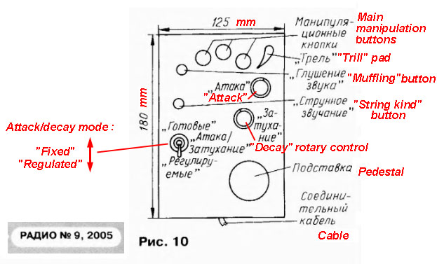
The left hand of musician rests on the control panel, an approximate shape of which is shown in the figure:


All controls (handles, buttons, the pedestal, as well as the front side) are made of dielectric materials.
There is a special metal pad, electrically connected to the "ground" of circuit, to which the musician can touch with his finger.

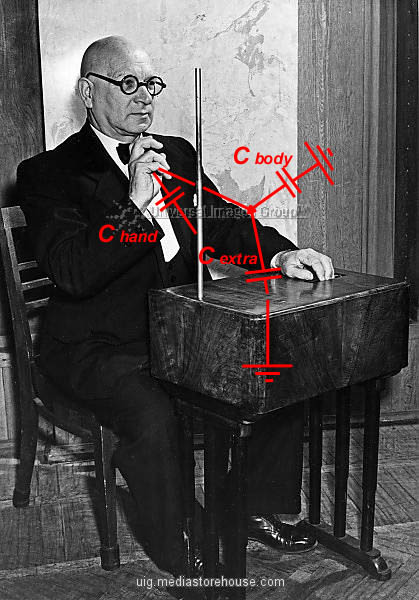
Initially, the hand-to-panel capacitance  C extra  (~100 pF, very approximately) is added to the body capacitance  C body (~100 pF), and this total capacity is connected   in series to hand capacitance C hand .  Due of this serial connection, the capacitance perceived by antenna will be slightly less than  C hand.

When touched the pad, the musician is connected to "ground" of the circuit; so we can put  C body + C extra = infinity (this is not entirely correct because of non-zero body/dermis resistance). As a result, the antenna will see the true (i.e. not reduced)  "hand capacitance"  and the pitch will be slightly increased.

Here are some Kovalsky system theremins (notice the visual pitch indicators on the board):


Posted: 10/25/2017 6:56:10 PM
dewster

From: Northern NJ, USA

Joined: 2/17/2012

Thanks ILYA!  Very nice explanation, beautiful instruments.  Pitch display!

Interesting how Kovalski, Martenot, Le Cain, etc. all go for very similarly looking expressive left hand controls.

Posted: 11/3/2017 9:05:47 PM
JPascal

From: Berlin Germany

Joined: 4/27/2016

ILYA,

searching for a math formula describing the static antenna capacitance of a rod I used your measurements on the beginning of this thread to validate what I found.

Your experimental results are in good accordance to a formula of russian authors in a publication from 1971:

l = antenna length; r = rod radius

So I will use this formula for the next time in my own simulations and experiments. 

You must be logged in to post a reply. Please log in or register for a new account.