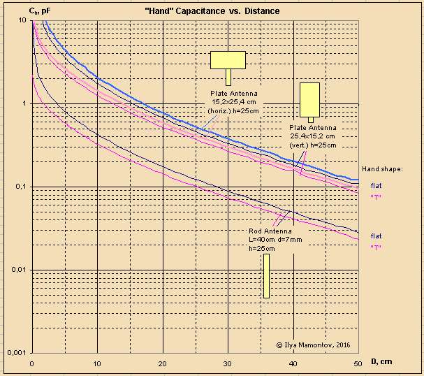
Lot of formulas for the capacitance between two bodies on long distances contain a ln() member. But this is not the point. As you could see, I use the logarithmic Y axis for C (that's my "optics"). This is due not only of huge range of C. If we see a straight line on such the graph, the straight line will be obtained (under certain conditions) on the pitch graph too.
Measuring Antenna Capacitance
"Lot of formulas for the capacitance between two bodies on long distances contain a ln() member." - ILYA
The approximate capacitance between two spheres of radius r separated by a large distance d is:
C = ( epsilon * 4 * pi * r^2 ) / d
Which is the same (in terms of area) as the parallel plate approximation for very close, large circular plates:
C = ( epsilon * pi * r^2 ) / d
It's understandable that geometry is meaningless at a distance, where it's all surface area and linear. And up close plates are linear.
This shows up all over the place for all kinds of geometries. This is mutual C, not total C (mututal + intrinsic) as seen by the tank inductor. Mutual C increases as the hand approaches the antenna, but intrinsic C actually decreases, due to antenna intrinsic field lines being directed away from the larger environment to the approaching hand. But the effect of mutual C dominates, and intrinsic C isn't simply a constant (as I naively imagined it was before I started simulating with FastCap).
I haven't specifically simulated this, but the C "pooping out" you are seeing as the hand nears the antenna is likely almost entirely geometric, because the mutual C between the hand and the ends of the antenna is fairly constant (i.e. doesn't contribute to C change). This pooping out is advantageous for heterodyning Theremins, as it tends to counteract squealing (it partially ameliorates the nearfield deviation of the heterodyned approximate exponential response) but you don't want it in a digital Theremin.
"If we see a straight line on such the graph, the straight line will be obtained (under certain conditions) on the pitch graph too."
I haven't worked through the math but I can imagine that that is probably true. So you are using log x because the ear perceives pitch logarithmically, which is what I was asking.
ILYA, just for the heck of it I went back to both my simulated data (virtual Clara in FastCap) and my measured data (my real body/arm/hand) for the EWS pitch antenna geometry:
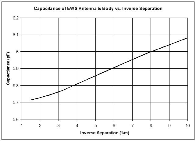
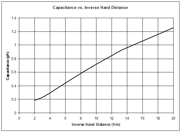
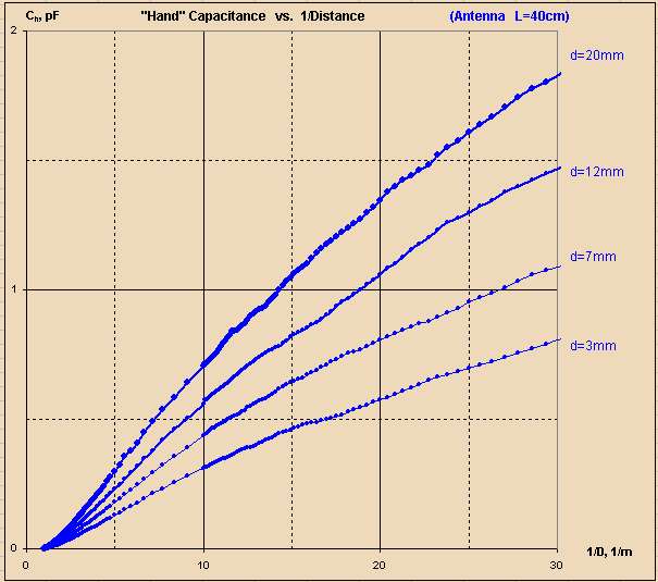
The top graph is my sim data, the middle graph is my real data, the bottom graph is your real data. Since the EWS antenna diameter is ~10mm, I believe the curve to look at with your data lies somewhere between the two middle curves (7mm and 12mm).
The x axes are all different here, and they are 1/d so they don't naturally scale by eye, but if we look at just the [0:10] 1/d region they are essentially the same in terms of shape and delta C (~1/2 pF). And the middle and bottom graphs over [0:20] 1/d show similar curvature and delta C (~1pF).
With this confirmation, i.e. the strong similarity and consistency between the one theoretical (which I actually trust the most) and the two independent actual measurements, I consider this area of study to be known to the degree necessary to utilize the data for detailed design and analysis.
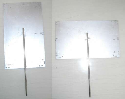
Was busy this week, so have only prepared some hand shapes and a plate antenna (with variable orientation):
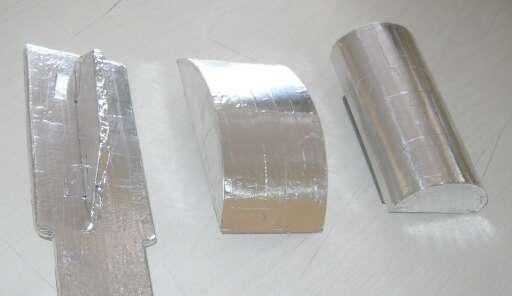
At the moment the data for "T-shaped" (the rib simulates the deflected little finger) and "flat" hands are ready:
And especially for folks with 1/x optic :)
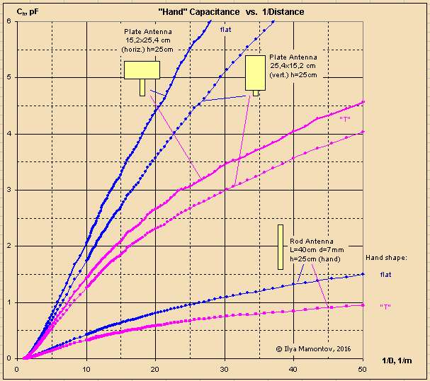
ILYA, small point: I think the plate antenna in "horiz." mode is more analogous to the same plate antenna in "vert." mode on a real Theremin due to the way the "hand" approaches the antenna horizontally (whereas real players tend to approach the antenna vertically). I think this is generally true for all of your measurements.
I would have guessed the "T" hand would look more linear than that, but I haven't tested this geometry. Are you measuring distance as the gap between the closest points of the hand and antenna?
Massive increase in sensitivity with a plate, and plate to plate C is amazingly linear in a 1/d sense.
Mutual C + Intrinsic C = Total C
As I note over on my digital Theremin thread, antenna intrinsic capacitance is not fixed, but varies as the hand approaches and recedes. Think of one of those lightning balls: when sitting alone, the discharges are evenly distributed spherically, but as a hand approaches the nearest discharges veer towards the hand. Same with antenna intrinsic capacitance, it is highest when the antenna is sitting alone, but decreases as a hand approaches. Decreasing intrinsic C with increasing mutual C cancel each other out to some degree unfortunately, lowering absolute sensitivity. On the up-side, the opposite curvatures of the intrinsic C and mutual C tend to linearize the total C 1/d response.
One can see this clearly in a FastCap simulation:
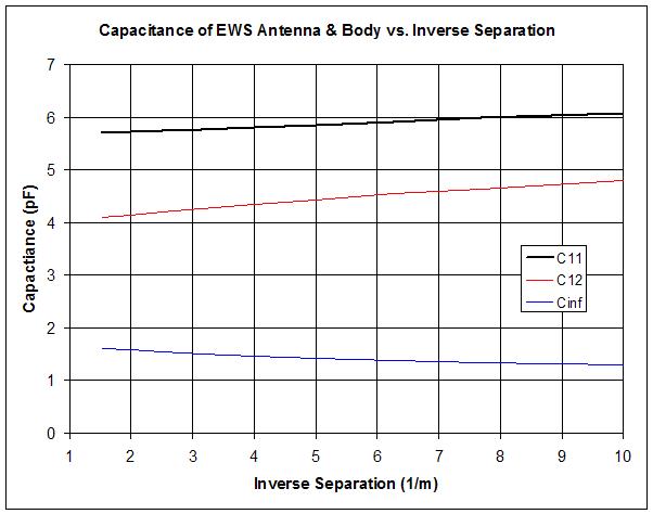
Above, the intrinsic C is Cinf, the mutual C is C12, and the total is C11, all plotted against the inverse of the distance. The model is a spherical hand attached to a full body standing on a ground plane disk, "playing" a EWS rod antenna. As the hand approaches (as 1/d increases) intrinsic C decreases, mutual C increases, and total C increases due to the dominance of the mutual C. The change in intrinsic C works against the change in total C, and total C is what the LC tank "sees." The change in total C is less than the change in mutual C, but the change is more linear in a 1/d sense.
Not sure how one might measure the above in the real world; perhaps AM transmission through the mutual C would reveal it's value? Then subtract that from the total C to get intrinsic C.
Total C response in the near-field boils down to geometry-based intrinsic C vs. mutual C. Far-field total C response is largely non-geometric, and so boils down to surface area of the hand and antenna.
"Are you measuring distance as the gap between the closest points" - dewster
Yes, I always meant the gap.
"whereas real players tend to approach the antenna vertically" - dewster
IMHO that's absolutely true for plate theremins like the Harrison instruments. Different thereminists prefer different techniques.
Effect of hand geometry.
In addition to flat hand, I have made a few of removable pads (lets call it "T", "D" and "P"):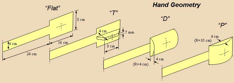
The case "T" simulates the "deflected little finger" or a hand orientation "by edge".
Results of measurements (for dewster's flat antenna and 7 mm/40 cm rod) are presented below: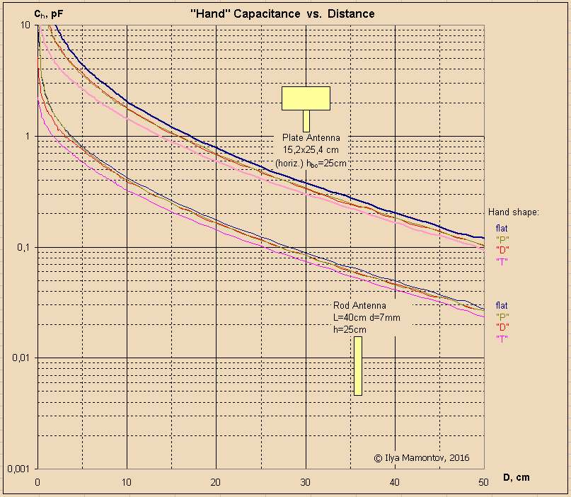
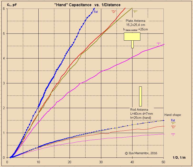
As you can see, the "D" and "P" charts are practically the same (except the case of rod antenna: the curve "P" goes from "D" to "flat" in near field).
Obvious conclusions:
1. The plate antennas significantly exceed on sensitivity the rod antennas (all the curves has the same slope, but the plate's curves are located higher, that means the greater dC/dX using the logarithmic Y axis).
2. The flat "hand" gives the highest sensitivity. Any bulges reduce sensitivity, especially the "deflected little finger".
Further:
3. In the far field, all the antennas and hands demonstrate the same slope angle (in terms of logarithmic Y and linear X axis).
4. In the near field the deflected finger (the case "T") has the strongest impact - it improves the linearity because it slightly postpones the moment of catastrophic growth of capacitance, both for plate and rod antennas.
5. The convex shapes also improve the linearity, but much less.
6. Paradoxically, the hand clenched into a fist (the "P" case) degrades the linearity of rod antenna. In practice it may be unnoticeable, since the deflected fingers (or edge of hand oriented toward the antenna) give the opposite effect.
----
Loop antenna. 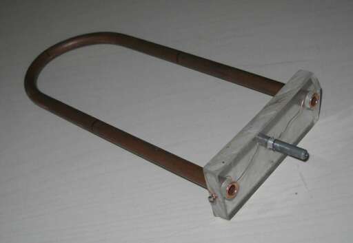
The loop has dimensions of 9.8 x 23 cm (almost like EWS) and is made of a 10 mm pipe. A short (2 cm length 6 mm diameter) holder is electrically connected to loop by thin wire.
Dependencies: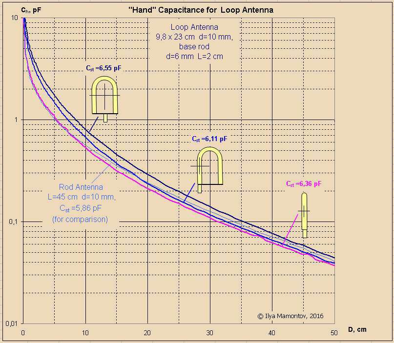
The first case - the center of the hand approaches the center of the loop.
The second case - the center of the hand approaches the center of a rod. Sure the musician makes a cross between these two cases.
The third case - the center of the hand approaches the center of a rod, but from the lateral direction.
Also, the curve for EWS pitch antenna is presented for comparison. The data for L=45 cm and d=10 mm was obtained as a result of linear interpolation of cases L=40/60 cm and d=7/12 mm).
ILYA, interesting that you're testing the loop antenna shape too, thanks for doing that. Any reason for the multiple posts?
Since C is strongly related to area, I wonder how many "fingering techniques" used by Thereminists employ this? It's true that peeling a finger off of your fisted hand and pointing that finger at the antenna will reduce the main distance, but it will also increase the area of the hand itself, and both of these will increase C. Though I'm sure the reduced main distance has the most effect.
"Any reason...?"
No reasons. My and forum engine troubles.
----
Have tried to approximate the dependences by analytic functions, in all the distance range, but without success. Either a good approximation in the near field by relation kind of C=a*ln(b/distance +1), either a good approximation in the far field by formula C=a*(1/distance)^1.7 (inverse distance in power of 1.7, not 1!).
You must be logged in to post a reply. Please log in or register for a new account.

