LC Tank / Linearizing Coil Excel Simulation

Posted: 2/11/2013 12:03:29 AM
dewster

From: Northern NJ, USA

Joined: 2/17/2012

Yet another spreadsheet up:
http://www.mediafire.com/?59nt74bqdcwbowd

- Revision History -
2013-02-10 : v6
> Fixed many incorrect references to "Bode" worksheet values in the "Linearity" worksheet VB code.
> Phase unroll in "Bode" and "Linearity" is now a phasor rotation followed by angular offset.
> Added single and double coat wire diameters to "Inductor Design" worksheet.
> Fixed EWS "Refrerence Designs" parameters (xfmr secondary inductance was wrong).
> Added "BUDGET" reference design.
> Added reference to the air core coil & transformer design program "Inca" to "Transformer Model" worksheet.

Posted: 2/16/2013 1:21:31 AM
dewster

From: Northern NJ, USA

Joined: 2/17/2012

New version 7 up:

http://www.mediafire.com/?olkiz89tjhi29ux

- Revision History -
2013-02-14 : v7
> Updated Theremin circuit to include Rser.
> Added "CAPLESS" reference design.
> Added falling phase criterion to "Bode" resonance phase detect.

2013-02-12 : v6
> Applied some techniques to VB code to speed it up (from http://www.avdf.com/apr98/art_ot003.html)
> Doubled the data points in "Bode" to get better resolution.
> Added PVC Schedule 40 data to "Inductor Design" worksheet.

New basic circuit which now includes Rser, and has the winding directions more realistically oriented for series tank transformer designs (both low voltage ends on the left, both high voltage ends on the right):

And I believe I've discovered a new tank mode!  It's "CAPLESS" in the reference design worksheet.  Looking at the above circuit, imagine Cpar and Cser removed, Rin replaced with a wire, Rser set to around 470 Ohms, Vin = 3.3V p-p square wave, and Lp = Ls = Leq = ~4mH.  With this configuration it seems the external capacitance alone (except for coil parasitics) sets the resonance point, which makes it the most sensitive I've encountered.  It also has a large and well defined resonance phase region, and that phase is 0 degrees @ Vser.  Haven't tested it in circuit because I'd need to wind that transformer, and to do that I need to build a rudimentary winder.  I think it is possible to form the secondary winding and EQ winding with one long coil, with the primary wound on top at the left end, so the secondary leakage inductance forms the EQ coil on the right.

All Theremin pitch oscillators I've seen are an LC tank that resonates on its own, perturbed by external capacitance, often through an EQ coil.  The EWS has a large capacitor and small inductor in a parallel resonant configuration, my AFE has a large inductor and tiny capacitor in a series resonant configuration.  In both cases the external capacitance can't completely dominate the tank LC operating point, which gives limited sensitivity.  This new mode has no tank capacitance, so there's no ratiometric reduction in sensitivity.  Though I guess it remains to be seen whether it actually works, and if so stable enough for Theremin use.

I should also add that the coil currents are fairly low in this new mode (~5mA at resonance with the above component values).  (In comparison, the EWS tank coil current can be quite high, particularly if slightly mistuned.  This is perhaps why the current mirrors in the EWPro oscillators increase stability, by placing an upper limit on the tank current and therefore limiting the self heating of the oscillator transistors.)  Another nice thing about this new mode is Vser p-p is roughly 1/2 the supply voltage, so a voltage divider isn't needed in order to feed it to the phase detector circuitry.  (My AFE requires a capacitive voltage divider here.)

Posted: 2/16/2013 2:51:06 AM
FredM

From: Eastleigh, Hampshire, U.K. ................................... Fred Mundell. ................................... Electronics Engineer. (Primarily Analogue) .. CV Synths 1974-1980 .. Theremin developer 2007 to present .. soon to be Developing / Trading as WaveCrafter.com . ...................................

Joined: 12/7/2007

Hi Dewster,

That is facinating and will take some time for me to fully assimulate - just looking at it and wondering about modeling the Lev oscillator using it .. It should do the job (?) - not sure exactly what you mean by "This new mode has no tank capacitance"  - Presumably you are talking about the mode when Cpar and Cser are not fitted, but one can fit either if one wants .. Im sure it will all become clear - I will download this and have a play with it! ...

I have a Lev board (the PCB's arrived today - not my ideal board, but I managed to fit extra components on a PCB I designed for another project, so hopefully it will work despite less-than-perfect layout) and with it I should be able to compare simulation to reality soon..

Fred.

ps - Having some problems with "type mismatch" run-time errors when I set coupling low, same message when [use bode] button pressed, but this is easily bypassed... PC crashed and I lost the file I was recording all this stuff to.. I will email you if I cannot find my error.


Posted: 2/16/2013 5:38:53 AM
FredM

From: Eastleigh, Hampshire, U.K. ................................... Fred Mundell. ................................... Electronics Engineer. (Primarily Analogue) .. CV Synths 1974-1980 .. Theremin developer 2007 to present .. soon to be Developing / Trading as WaveCrafter.com . ...................................

Joined: 12/7/2007

Just been looking at your Capless mode - Its impressive! - There is such high sensitivity there it is almost unusable, but if one reduces sensitivity with a small Cblock, I think you might really be onto something!

But I must admit I may be talking out my RS - Truth is that its not easy to visualise the operation, I have my head so "corrupted" with the ideas underpinning the usual ways, that im having problems - I see it for a moment, then I dont then I do then I dont... ;-)

Fred.

Posted: 2/16/2013 5:51:38 AM
dewster

From: Northern NJ, USA

Joined: 2/17/2012

"In particular, the coupling value for the tank transformer appears to be far more critical than I had expected - in fact, I dont think I can trust it.. I get best linearity with weaker coupling (down to 0.6) but if I go below 0.5, I get a straight line and resonance of 0.9Hz ;-)"  - FredM

The "Linearity" worksheet necessarily uses a different method to find resonance, and depending on the circuit can be very sensitive to initial frequency.  You should enter everything on the "Bode" sheet, use it to find resonance, then transfer the results over to the "Linearity" sheet.  You may have to lower "Freq Start" on the "Linearity" sheet a bit to catch the right phase point.  Lowering "Freq Step" on "Linearity" might help too, but will make the simulation take longer.  If it doesn't catch and seems to be taking forever, hit the escape key.  You may have to close then open the spreadsheet to get the VB to work again after that though (still working on that).

Not sure why you're getting an error during the data copy.  For simulation times I'm getting about 5 seconds simulation on "Bode" and maybe double that on "Linearity" with the reference designs (dual core AMD 1.8 GHz).

"What are the "Linearity offset" and "linearity gain" about? Also the "linearized" plot? I dont understand these."

They apply a second order polynomial correction to the data.  "Linearity Gain" is the gain of the square term, "Linearity Offset" is simply an added constant.  The square term affects linearity near the antenna, the offset mostly far away but over the midrange as well.  These seem to track well with changes to the "Beat Null" point, and I intend to test this method for linearity down the road.  It's not completely ideal, but it's pretty simple, so the average user may be able to adjust them without too much fuss.

Posted: 2/16/2013 6:21:43 AM
dewster

From: Northern NJ, USA

Joined: 2/17/2012

Fred, if you find any circuit giving any better linearity than another I'd be interested in the details. 

It's my current unsubstantiated feeling that nothing really linearizes anything, it all gets swamped by the result being the slight difference between two huge numbers or frequencies.  In particular, the double resonance of the EW doing anything to improve linearity I feel is likely a myth.  But perhaps I've just been simulating too long with an insufficiently detailed antenna / hand model.

Posted: 2/16/2013 6:31:59 AM
FredM

From: Eastleigh, Hampshire, U.K. ................................... Fred Mundell. ................................... Electronics Engineer. (Primarily Analogue) .. CV Synths 1974-1980 .. Theremin developer 2007 to present .. soon to be Developing / Trading as WaveCrafter.com . ...................................

Joined: 12/7/2007

Thanks Dewster,

Glad you got that posting - I went to do an edit to it and somehow deleted it instead..

"They apply a second order polynomial correction to the data." - Ok, so these apply to a system (theremin) capable of implementing this correction (ie, digital) and are of no significance for other simulations.. am I right?  ... Shame, they give much better linearity ;-) - If you can actually implement this and achieve what the simulation is showing, I would say you are damn close!

Fred.


Posted: 2/16/2013 6:51:21 AM
FredM

From: Eastleigh, Hampshire, U.K. ................................... Fred Mundell. ................................... Electronics Engineer. (Primarily Analogue) .. CV Synths 1974-1980 .. Theremin developer 2007 to present .. soon to be Developing / Trading as WaveCrafter.com . ...................................

Joined: 12/7/2007

"Fred, if you find any circuit giving any better linearity than another I'd be interested in the details. " - dewster

Not seen anything which betters yor polynomial corrected results.

I do know that linearization does occur, in practice, when on has a "correctly" tuned antenna working with a "correctly" tuned tank.. I would be forced to acknowledge this even if the only "explanation" for it was something from celtic mythology ;-)

When it comes to simulating this, I have never been able to get absolutely convincing results. I believe that factors such as arm capacitance must be responsible for the better "fitting" I have seen - that, in fact, one may find if one got a perfect psreadsheet result, this would not equate to perfect actual linearity... Not unless one included these other factors in the calculation.

Other factors which really make matters worse can be the proximity of the theremins ground contributing to the total hand capacitance like a 2 plate capacitive sensor does.. Good grounding (or lack thereof) which makes the players coupling to ground insensitive to change in their ground goupling as a function of proximity, probably contributes more to linearity than anything else could.

Sorry - got interrupted and had to post quickly... I continue:

I have certainly seen definite effects on linearity as the result of changing the EQ inductance and matching the tank to "correctly" interface to this.

The best "playground" for this was with my H1 theremins - Linearity was not a primary objective - they werent at all bothered by this, and I chose the EPE-2008 front end which was supposed to have better linearity than the standard SC which had no EQ coil.. All this EPE design did was tack a coil onto the SC front end.. It was abysmal. I first used cheap inductors, then changed these to good inductors - no difference (except for lower thermal drift) - In fact, removing the EQ inductor made virtually no difference to linearity - in some cases the linearity seemed better without EQ.

Then I modified the tank drastically - tacked another inductor in parrallel with the primary inductance (tacked it across the IFT) to reduce the total value, and added a capacitor to bring the frequency back to that of the reference oscillator (which I didnt change), and changed the series blocking capacitor to adjust sensitivity..

The difference in playability (which I am sure was due to linearity) was astounding ... But I never actually measured the linearity - I did all this quietly and "secretly" while the show was going on, taking each theremin in turn and swapping the modules and antennas (to which the EQ inductors were bolted) - Fortunately I had designed the theremins so that it was easy to swap things (the theremin itself was in a tabbed plastic box that fitted into a cutout in the speaker enclosure, and could be removed with 4 screws and one connector, and the antenna assembly lifted off after removing 4 screws, and contained the inductor and a magnetic connector which self-located to its mating magnet)

It took me days to complete the modifications on all the theremins I had parts to modify (10 of the 16) - I was able to compare modified and unmodified theremins during that time, and my belief that the modified ones were far better was "confirmed" by the couple of people who came every day to play, and who chose their favorite theremin, always from the modified ones..

Then, one morning, I came to the show and powered up the theremins, and they were all terrible! - in fact the unmodified ones seemed more linear than the modified ones. By lunch time, after having removed some modules and antennas, I was at my wits end - they behaved as they should.. But put them back into their boxes and they were cr*p.

The electrician came over to me as I was miserably eating lunch and proudly told me that he had tidied up (removed) my ground wires.... ! ..... Back when I was installing the theremins, none of the specifications had been followed, so I wired up the power and seperate ground wires as best I could... with wire reluctantly given to me by this electrician who told me I was doing everything wrong.. I had wanted (specified) for each theremin to have a seperate ground wire going back to a common ground point.. but there wasnt enough cable, so I was forced to daisy chain them...

The theremins interacted like hell, and I ended up cutting the ground wires leaving a gap of about a foot - these became "ground antennas" which had enough coupling to the structure of the hall to provide a good ground field, and by disconecting the common (galvanic) grounding between the theremins their interactions dropped from being impossible to being "occasionally bothersome" between only two theremins.

"thanks" I said, LOL - I was so relieved that I didnt even feel angry - I put some aluminium foil connected to the ground inside the plinths the theremins were standing on, and everything worked again.

At that time I had never attempted to simulate EQ response accurately - I thought that I understood the EQ mechanism, but actually my understanding was shoddy - Before I got into debugging the EPE I really didnt have a clue.. If I had had a clue (and if I had had more than a few weeks to build the theremins from when I actually got the order) , I would never have gone for the EPE front end!

Fred.

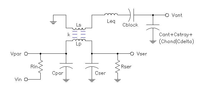
note: So far, based on breadboard tests in far-from-ideal conditions, It appears that the best passive front-end in terms of linearity that I have ever played with (certainly as good as any passive* equalizing circuit I have built) is the "clone" derived from the Clara-min schematic using RCA inductance and capacitance values, and using an air-coil transformer wound on a EFD25/13/9 former, 450mm x 15mm copper tube for antenna, and a IFT wired as 1.2mH adjustable inductor in parallel with one winding of this transformer to facilitate trimming, and 70mH of 6300 series EQ inductors..

The above transformer has total measured inductance of 680uH, and the IFT is across the upper winding only.

* as in, no active electronics or frequency monitoring / correction circuit.

But I am cautious - The above is what I wanted to see - So I wont trust it until I have verified it!

Posted: 2/16/2013 3:34:56 PM
dewster

From: Northern NJ, USA

Joined: 2/17/2012

"Not seen anything which betters yor polynomial corrected results."  - FredM

Like you, I think the antenna hand model is probably too simplistic.  Regardless of what it is applied to the simulation results are usually the same, three or so octaves of relative linearity, cramping in the near and far fields.

"I do know that linearization does occur, in practice, when on has a "correctly" tuned antenna working with a "correctly" tuned tank.. I would be forced to acknowledge this even if the only "explanation" for it was something from celtic mythology ;-)"

If you're talking about a parallel tank, I think this is true.  But I think they are difficult to tune and if mistuned give poor results.

Fred, that grounding experience sounds like it was a nightmare!  Sometimes information is perhaps too hard won.

"...the Clara-min schematic using RCA inductance and capacitance values, and using an air-coil transformer wound on a EFD25/13/9 former, 450mm x 15mm copper tube for antenna, and a IFT wired as 1.2mH adjustable inductor in parallel with one winding of this transformer to facilitate trimming, and 70mH of 6300 series EQ inductors.."

Lots of detail!  Interesting way of trimming the frequency.  Big EQ coil!  (BTW, by my calculations the Keppinger Theremin EQ coil is around 30mH.)  I like the mostly air core tank, do you think the 6300s will contribute significant drift?  (BTW, I took a damaged 6310, cut two of the doughnut windings off and wired the free end of the remaining doughnut to the free terminal.  Wound ~100 turns of ~30 AWG over the now empty spot and measured k, the coupling factor, of around 0.53, so the doughnuts are only moderately coupled, which makes sense due to the huge air gap, but was still something of a surprise to me.)

Posted: 2/16/2013 10:04:20 PM
FredM

From: Eastleigh, Hampshire, U.K. ................................... Fred Mundell. ................................... Electronics Engineer. (Primarily Analogue) .. CV Synths 1974-1980 .. Theremin developer 2007 to present .. soon to be Developing / Trading as WaveCrafter.com . ...................................

Joined: 12/7/2007

"Fred, that grounding experience sounds like it was a nightmare!  Sometimes information is perhaps too hard won." - Dewster

Oh, I dont think so.. It all contributes to making life more interesting! ;-) ... If one didnt have "horror" stories like that, what tales would you be able to tell to bore people with when you get old ?  LOL ;-)

And actually, I was really creating my own drama anyway - The customer was perfectly happy with my theremins whether people could "play" them or not! - I was in panic because I had a set of standards I was imposing on myself.. I had "no reason" to undertake the modifications except my passion and my misplaced sence of "duty".. The £30 the inductors cost me could have been pocketed - I had made a big loss on the damn instruments even before I modified them!

Fred. 

You must be logged in to post a reply. Please log in or register for a new account.