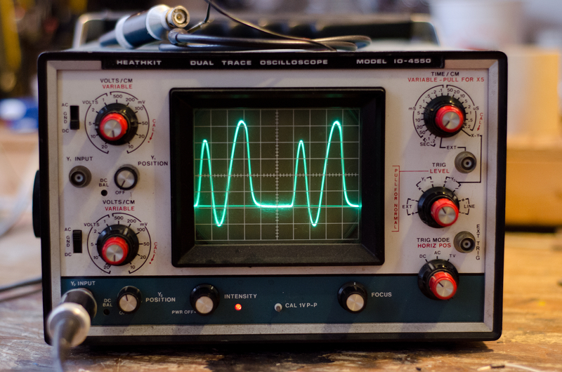
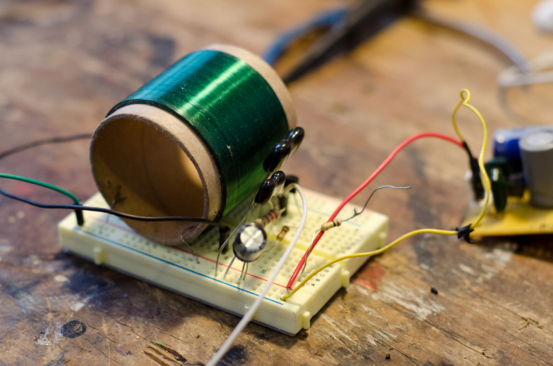
Actually - :-( [Please note - everything I say in the following may be wrong - this is exploratory only!]
The waveforms from the oscillator simulations, taken from S, and fed to the mixer - well, it doesnt represent the configuration of the RCA at all -
On the RCA, the grids of the oscillators are connected to the grids of the mixer.. There is no "S" connection - "S" would be the cathode - but the cathode is grounded.
I am going to try to sim a more exact replica of the triode oscillator using a fet - Watch this space.
Update 1:
Ok - Ran the sim with the source resistor shorted to ground - the gate now has an aproximately 1/2 wave rectified sine with a 'bump' on its flat-line.. No real point in pasting this here, as what actually appears will depend on lots of stuff related to the models.. but the waveform on the gate is almost identical to what it is with the source resistor fitted.
Heres the dillemma - Dominiks waveforms look lovely, are taken from a low-Z source, are ideal - It they were representitive of real RCA waveforms, well, there wouldnt be much more to do..
But we are (IMO) starting to gather too many unknown variables - In the process of this investigation we are discovering things which are useful - and things which may sound great and be usable in theremins .. But we dont know if we have a "RCA" waveform, or anything close - And we dont really have any exact idea of what we are looking for - so we might even see it and miss it..
Update 2:
Some more notes on oscillator simulation:
The reason why the G and S waveforms are not the same with a S resistor (which should be a follower of the G signal) is that the gate is an input terminal - its waveform determined by the LC circuit feeding it.. The Source follows this gate waveform over its active region, but saturates with the circuit I have given.
If biasing and levels are correctly set, a nearly true, low Z replica of the gate signal does appear on the source. I am redesigning the oscillator to facilitate this -


