Theremin Circuits Scratchpad

Posted: 10/12/2012 6:15:32 PM
Chobbs

From: Brooklyn,NY

Joined: 12/1/2009

I dug out the scope and was playing around a bit this morning-  Inspired by Dominik-

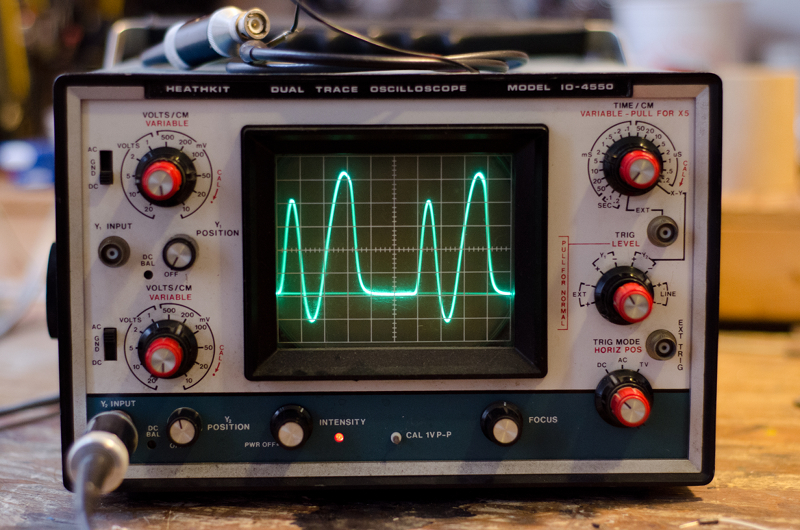
here is an image of the wave at  S  on my test fet oscillator using (more or less) RCA coils-  running at 173khz. 

looks similar to Dominik's, but a little different. At D, it looked about the same.  I dont have any time now but Ill try to get to the RCA this weekend.

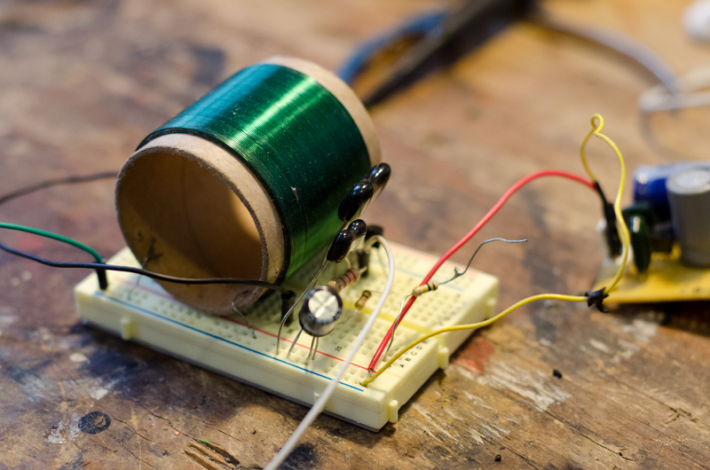
Here's my coil:


Posted: 10/12/2012 7:18:44 PM
FredM

From: Eastleigh, Hampshire, U.K. ................................... Fred Mundell. ................................... Electronics Engineer. (Primarily Analogue) .. CV Synths 1974-1980 .. Theremin developer 2007 to present .. soon to be Developing / Trading as WaveCrafter.com . ...................................

Joined: 12/7/2007

"looks similar to Dominik's, but a little different. " - Chobbs

Now that is REALLY interesting - Your waveform is a lot closer to the waveform from my simulation!

- Which would make sense if the ferrite charactaristics were influencing Dominiks waveform, as my inductor models do not deal with anything fancy like the saturation of ferrite..

I am really surprised!

Fred.

Ps - Your coils are a work of art! - and you are managing to get your 'scope to trigger on the waveform and display beautifully.

pps.. I am not able to get Dominiks waveforms from the simulation of the mixer, no matter what input signals I feed it..

I strongly suspect that a lot of these are due to oscillator coupling - I suspect that the Lev oscillators facilitate a far greater degree of oscillator coupling / synchronisation before going unstable or into lock, than parallel tank designs - If this is true, then this could perhaps explain the rich harmonics at the bass end.

As I see it, the coupling of the lower fet S to the upper fet G via 100k may provide the signal which syncronises the oscillator connected to the upper fet G, to a complex signal appearing on the lower fet S - Not sure about this - a lot depends on the capacitor between the lower fet S and Gnd .. If this has a high ESL, then this could work.

Posted: 10/13/2012 5:00:58 AM
w0ttm

From: Small town Missouri on Rt 66

Joined: 2/27/2011

"As I see it, the coupling of the lower fet S to the upper fet G via 100k may provide the signal which syncronises the oscillator connected to the upper fet G, to a complex signal appearing on the lower fet S - Not sure about this - a lot depends on the capacitor between the lower fet S and Gnd .. If this has a high ESL, then this could work." Fred.

I think that nails the difference between our sim waves and real life.

The sim has perfect capacitors.

Posted: 10/13/2012 10:49:49 AM
FredM

From: Eastleigh, Hampshire, U.K. ................................... Fred Mundell. ................................... Electronics Engineer. (Primarily Analogue) .. CV Synths 1974-1980 .. Theremin developer 2007 to present .. soon to be Developing / Trading as WaveCrafter.com . ...................................

Joined: 12/7/2007

Actually - :-(   [Please note - everything I say in the following may be wrong - this is exploratory only!]

The waveforms from the oscillator simulations, taken from S, and fed to the mixer - well, it doesnt represent the configuration of the RCA at all -

On the RCA, the grids of the oscillators are connected to the grids of the mixer.. There is no "S" connection - "S" would be the cathode - but the cathode is grounded.

I am going to try to sim a more exact replica of the triode oscillator using a fet - Watch this space.

Update 1:

Ok - Ran the sim with the source resistor shorted to ground - the gate now has an aproximately 1/2 wave rectified sine with a 'bump' on its flat-line.. No real point in pasting this here, as what actually appears will depend on lots of stuff related to the models.. but the waveform on the gate is almost identical to what it is with the source resistor fitted.

Heres the dillemma - Dominiks waveforms look lovely, are taken from a low-Z source, are ideal - It they were representitive of real RCA waveforms, well, there wouldnt be much more to do..

But we are (IMO) starting to gather too many unknown variables - In the process of this investigation we are discovering things which are useful - and things which may sound great and be usable in theremins .. But we dont know if we have a "RCA" waveform, or anything close - And we dont really have any exact idea of what we are looking for - so we might even see it and miss it..

Update 2:

Some more notes on oscillator simulation:

The reason why the G and S waveforms are not the same with a S resistor (which should be a follower of the G signal) is that the gate is an input terminal - its waveform determined by the LC circuit feeding it.. The Source follows this gate waveform over its active region, but saturates with the circuit I have given.

If biasing and levels are correctly set, a nearly true, low Z replica of the gate signal does appear on the source. I am redesigning the oscillator to facilitate this -
Posted: 10/14/2012 10:53:43 PM
DOMINIK

From: germany, kiel

Joined: 5/10/2007

I am confused:

A)
I build an RCA coil (on a plastic tube) like those documented at Arthur Harrisons site (opposite winding directions, aha!), with matching inductivity values (not matching the documented 598uH each which Fred found out to be wrong, but about 160uH each and about 700uH in series). The osc won´t oscillate if the coil being wired like the given schematics transferred to Fred´s, (i mean the coils points 1-2, 3-4), but will oscillate if either 1-2 or 3-4 are connected inverted (e.g. 2-1, 3-4). Is this common or should it work in any case? Edit: Just noticed that the series inductivity cannot be measured/gives crude values if connected "wrong".

In the well operating mode: same behaviour and same waveforms like with the DIY can inductor..

B)
If the 100K from the lower FET S to the upper FET G is omitted i still get those kinds of waveforms. Ok, the timbre differs more or less – i just considered it as a further way to alter/sweeten the timbre and has been IN while being scoped.

As Charlies scoped and the simulated waveforms seem to be similar i suggest to treat my observations with caution. I don´t get it yet! This to "german efficiency" ;)

Posted: 10/14/2012 11:53:15 PM
Chobbs

From: Brooklyn,NY

Joined: 12/1/2009

Dominik-  Unfortunately....Art's oscillators are all wrong....wrong tube diameter, wire size, and # of windings.  The construction technique is correct,tho'.     Info here is acurate

should be about 170uH each  (like 170uh for the inner winding and like 178ish uH for the outer)

....and (I think that you caught this, but)  but the oscillator will not oscillate unless the windings are oppositely wound.   I found out the hard way!

Posted: 10/15/2012 12:33:54 AM
FredM

From: Eastleigh, Hampshire, U.K. ................................... Fred Mundell. ................................... Electronics Engineer. (Primarily Analogue) .. CV Synths 1974-1980 .. Theremin developer 2007 to present .. soon to be Developing / Trading as WaveCrafter.com . ...................................

Joined: 12/7/2007

Which "way" the coils are wound should only affect which terminals will need to be connected.. its all about the phase dots..

but yes, no need to rewind the coil (if you find there is such a need, I think the rules of physics would need some changes! ;-) simply swap the wires over on either the primary or the secondary (as in, one of the windings).

If you wind two coils on to pof each other in the same direction, the start of one winding  would have a "phase dot" on the schematic, and the ending of the other winding would have a "phase dot"..

If you grounded both windings on their "phase dot" ends, and put a signal into one, the signal out of the other will be the same phase as the in signal. Likewise, if you ground one 'phase dot' end, and the other 'no phase dot' end, the signal out from one will be inverted (180 degrees out of phase) to the other.

There actually is no such thing as winding a coil in the wrong direction - its a spiral - it actually doesnt have a 'direction' - all that anything "running along" the spiral has is a rotational direction - it is this "rotational direction" which matters from a perspective of inducing currents - and this rotational direction is defined by / can be changed by which end you are moving from / to - and with electrons, this is defined by which wires you connect to which end!

You need to BE an electron, and get dizzy! ;-)

Warning - the above only applies to simple un-tapped windings.. if you wind a coil, take a tap, then continue winding in the opposite direction - well, at best it wont work ;-) .. This is because whatever you induce from one direction will be countered in the other direction - This is how wire-wound resistors dont havev huge inductances - they are wound in a bi-filar manner so that mutual inductions cancel out.

Fred.

Posted: 10/15/2012 8:32:01 AM
DOMINIK

From: germany, kiel

Joined: 5/10/2007

Thanks for that! The three-finger-rule is getting back to my memory.

Posted: 10/18/2012 2:01:28 AM
Chobbs

From: Brooklyn,NY

Joined: 12/1/2009

Placing that order soon.   Someone give me a few suggestions for different  FETs to try. How about Dual FETs?   I looked but was overwhelmed with the choices.

Posted: 10/18/2012 8:55:53 PM
FredM

From: Eastleigh, Hampshire, U.K. ................................... Fred Mundell. ................................... Electronics Engineer. (Primarily Analogue) .. CV Synths 1974-1980 .. Theremin developer 2007 to present .. soon to be Developing / Trading as WaveCrafter.com . ...................................

Joined: 12/7/2007

Charlie,

I have not physically built anything yet - the only hands-on I have done is testing potential inductors and transformers. The waveforms you have shown cause me to think that the mixer is not too critical - The fets (2n3458) I used in my simulations should work - but probably best to use the ones Dominik actually used in his real circuit.

Personally, I dont think dual-gate fets are needed - But if you find any which are not SMD I would be most interested.

Fred.

You must be logged in to post a reply. Please log in or register for a new account.