

Introduction
Thanks to David Kean and the Audities Foundation in Calgary, Canada for providing me the opportunity to restore an original RCA AR-1264 Theremin and make these measurements and to Arthur Harrison for his schematics. Also thanks to Jeffrey Sparks for preparing the drawings of the cabinet and providing a valuable check of the measurements. His efforts in preparing and checking the drawings contributed significantly to their value. Thanks also to Andrew Baron for providing additional checking and measurements and to Robert Slagle for access to his instrument. The schematics and drawings are available for printing at 300 dpi on 8 1/2 by 11 inch paper as listed in the appendix.
During the restoration process, I measured all the component values and coil dimensions and measured the cabinet and made sketches of the construction details. Having just researched and constructed the electronics of a replica RCA Theremin, I knew what values and dimensions were not available and necessary for reproducing the instrument electronics and cabinet. The following table shows the critical values needed to duplicate the electronic portion of the instrument.
Coils, Transformers, and Various Components
By Mark McKeown
2006
| Terminal | |||
| 1-2 | R = 249 ohms | l = 13.4 mH (c) l = 11.4 mH (m) |
No. turns = 586 Wire Size 36 |
| Dia = 3.0 in | L = 4.40 in | Series capacitor 2200 pf | |
| 3-4 | R = 0.4 ohms | l = 8.9 mH (c) | No. turns = 8 Wire Size 22 |
| Dia = 3.0 in | L = 0.262 in | ||
| 1-2 | R = 597 ohms | l = 36.9 mH (c) l = 30.0 mH (m) |
No. turns = 1390 Wire Size 36 |
| Dia = 3.0 in | L = 10.43 in | Series capacitor 2200 pf | |
| 3-4 | R = 96 ohms | l = 20 mH l = 11.4 mH (m) |
|
| Dia = 0.963 in | L = 0.363 in | I.D. 0.550 in | |
| 1-2 | Dia = 1.5 in | L = 1.380 in | No. turns = 42, Wire Size 20 |
| Parallel capacitor 135 pf variable | |||
| 3-4 | Dia = 1.5 in | L = 1.380 in | No. turns = 42, Wire Size 20 |
| Parallel capacitor 500 pf, trimmer 100 pf | |||
| 1-2 | Dia = 1.5 in | L = 1.300 in | No. turns = 76, Wire Size 26 |
| Parallel capacitor 55 pf variable | |||
| 3-4 | Dia = 1.5 in | L = 1.300 in | No. turns = 76, Wire Size 26 |
| Parallel capacitor 1000 pf, trimmer 30 pf (This measured 30pf, but possibly should be 100 pf). | |||
| 1-2 | Dia = 1.5 in | L = 1.300 in | No. turns = 76, Wire Size 26 |
| 3-4 | Dia = 1.5 in | L = 1.300 in | No. turns = 76, Wire Size 26 |
| Parallel capacitor 1000 pf, Trimmer 100 pf | |||
| Primary R = 1085 ohms | Secondary R = 5.4K ohms | RCA Part No. GW-42 EE |
| Primary R = 973 ohms | Secondary R = 5.06K ohms | RCA Part No. GW-42 EM |
| Input R = 473 ohms | ||
| All have 1 volt minimum to maximum change: | |
| No load120 tube1 megohm | 2.5 volts maximum 1 volt maximum2 volts maximum |
Notes:
- Terminal numbers refer to the schematic of the RCA Theremin done by Arthur Harrison, rev 3-4-04. My terminals 3 and 4 on T2, T6, and T8 are reversed from the original.
- All wire sizes are for cotton covered (cc) wire, not enamel. Example: No. 38cc = No.34 enamel in diameter.
- (c) is a calculated value, (m) is a measured value.
- Values in ohms are DC resistances, not impedances.
- This is a draft document and I am not responsible for errors. Nobody is perfect. This document is for information only and historical value. Manufacturers commonly changed specifications and methods during production or used components on hand and one instrument may not be exactly like another.
- If you find errors or differences in values you have measured please let me know.
- Copyright © by Mark McKeown, 2005. It is ok to use this data but please give me credit. This was a lot of work and a unique opportunity to make these measurements.
Some of the coil construction details are available on Arthur Harrison’s website so I won’t discuss them here but I suggest that you use the exact dimensions I show in the table. Modified versions of his schematics are included below as a reference. His component labeling is used in this article.
Electronics
All electronic measurements were made with a digital multimeter and a Heathkit IB-3128 impedance bridge. Most of the available component values and measurements were correct but not all. I have tried to reconcile any differences and use the correct values in my table.
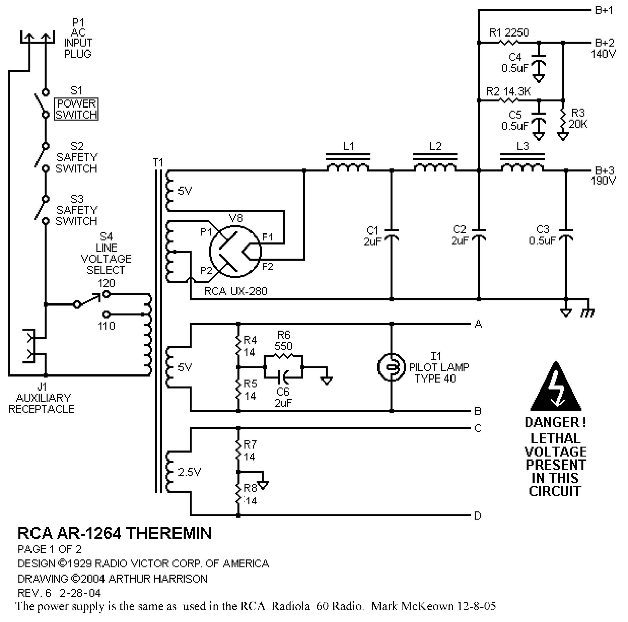
Power Supply (Figure 1) – Resistors R4, 5, 7, and 8 were measured at 14 ohms. The rest of the known data were correct. The power supply used by RCA in the Theremin is identical to the supply used in the RCA Radiola 60 radio that was produced at the same time. The only difference is that terminals 3 and 4 and terminals 6 and 7 are shorted together, removing one output voltage and grounding another terminal.
Main Chassis (Figure 2) – No physical measurements for the volume oscillator coil (T2) or the value of the parallel trimmer capacitor (C11) or capacitor (C12) were available until now. The concentrating coil located at the base of the pitch coil (T9) was reportedly 20 mH but I measured it at 11.4 mH. I used 20 mH in the replica I constructed and it functioned well. The pitch range of the replica was much more than the original RCA Theremin possibly because of this larger value coil. I reversed the coil in the RCA to see if the pitch range was reduced as mentioned in the RCA Theremin Service Notes and a significant decrease in range did occur. The trimmer capacitor (C18) in parallel with the fixed pitch coil (T6) measured as 30 pF but probably should be 100 pF. There may be a problem with the one I measured. The capacitor did have enough range to tune properly. The resistor from the grid of the variable pitch oscillator (V1) to the screen grid of the mixer (V2) is shown on the schematic as 10,000 ohms but I measured it as 15,000 ohms. This probably doesn’t make much difference but could have been adjusted at the factory to modify the timbre of the instrument. The 15,000 ohm resistor worked well.
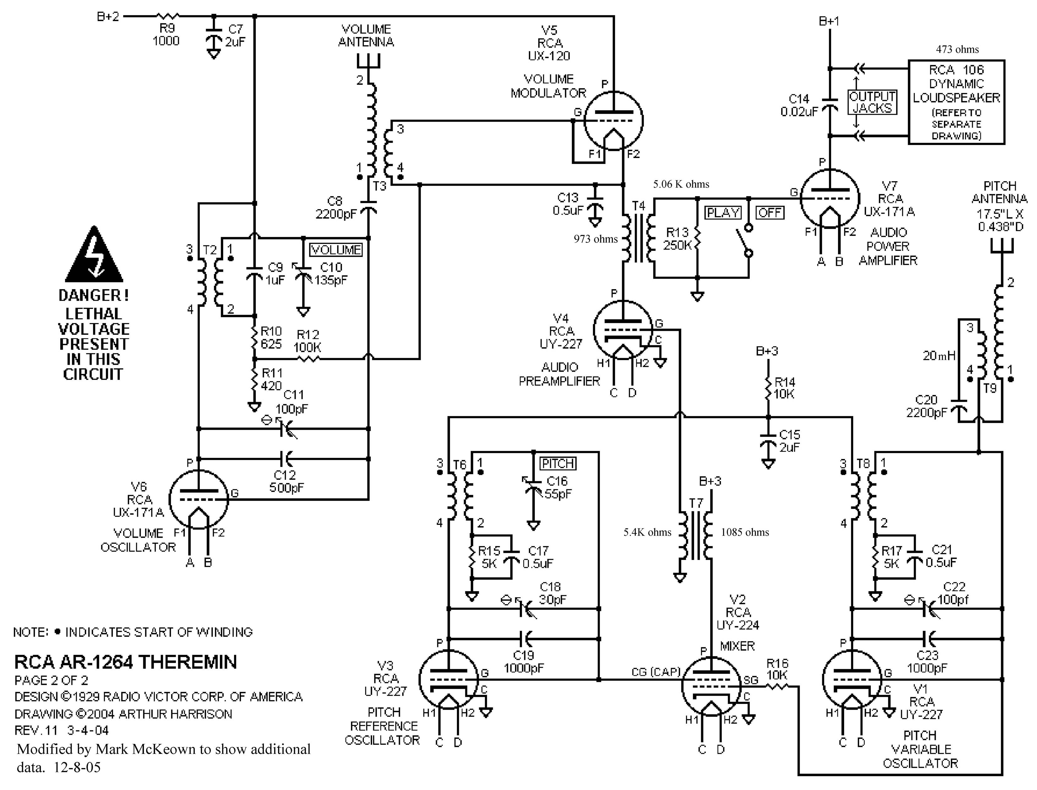
Andrew Baron informs me that the timbre of the instrument can be “tuned” by changing the pitch oscillator and mixer tubes to get the combination that sounds best to the listener.
Tubes for the RCA Theremin are still available from a variety of vintage tube suppliers although some of the tubes are expensive and are becoming scarce. An O1A tube can be substituted for the last audio amplifier tube UX-171A (V7). A UX-171A must be used for the volume oscillator (V6). A 31 tube can be directly substituted for the fairly rare 120 volume control tube (V5) or an adapter for a miniature 3Q4 tube can be constructed out of an old 4-pin socket although response time may be different.
Cabinet
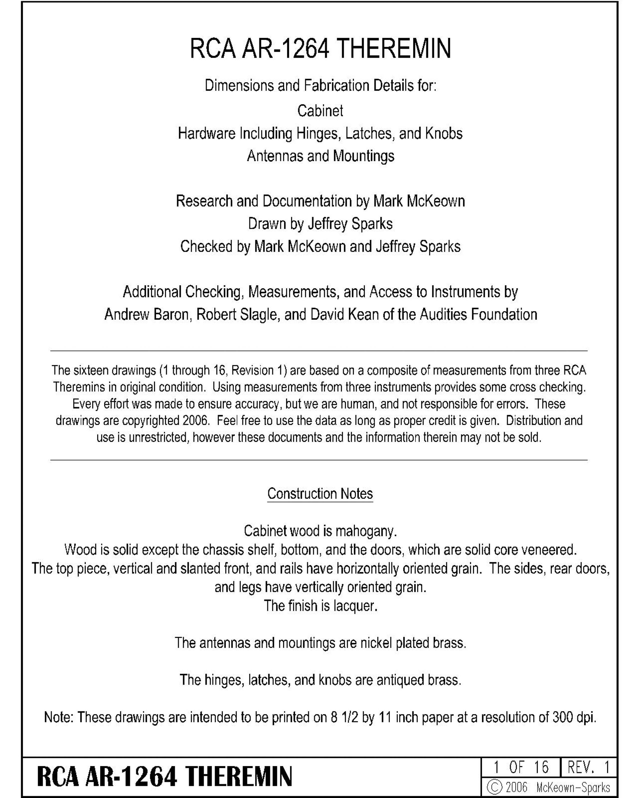
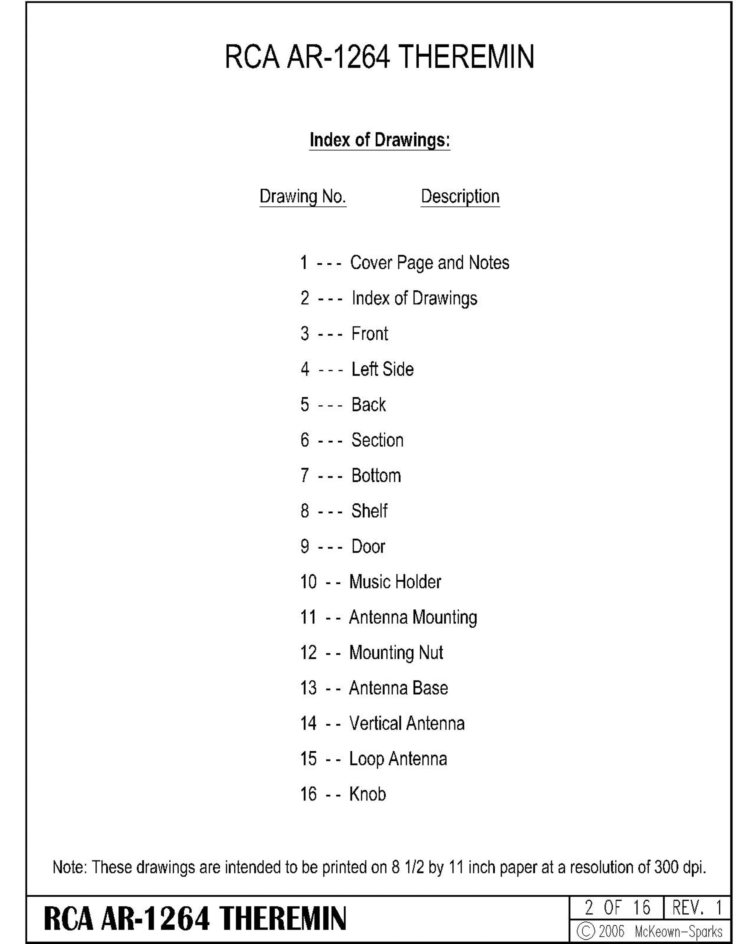
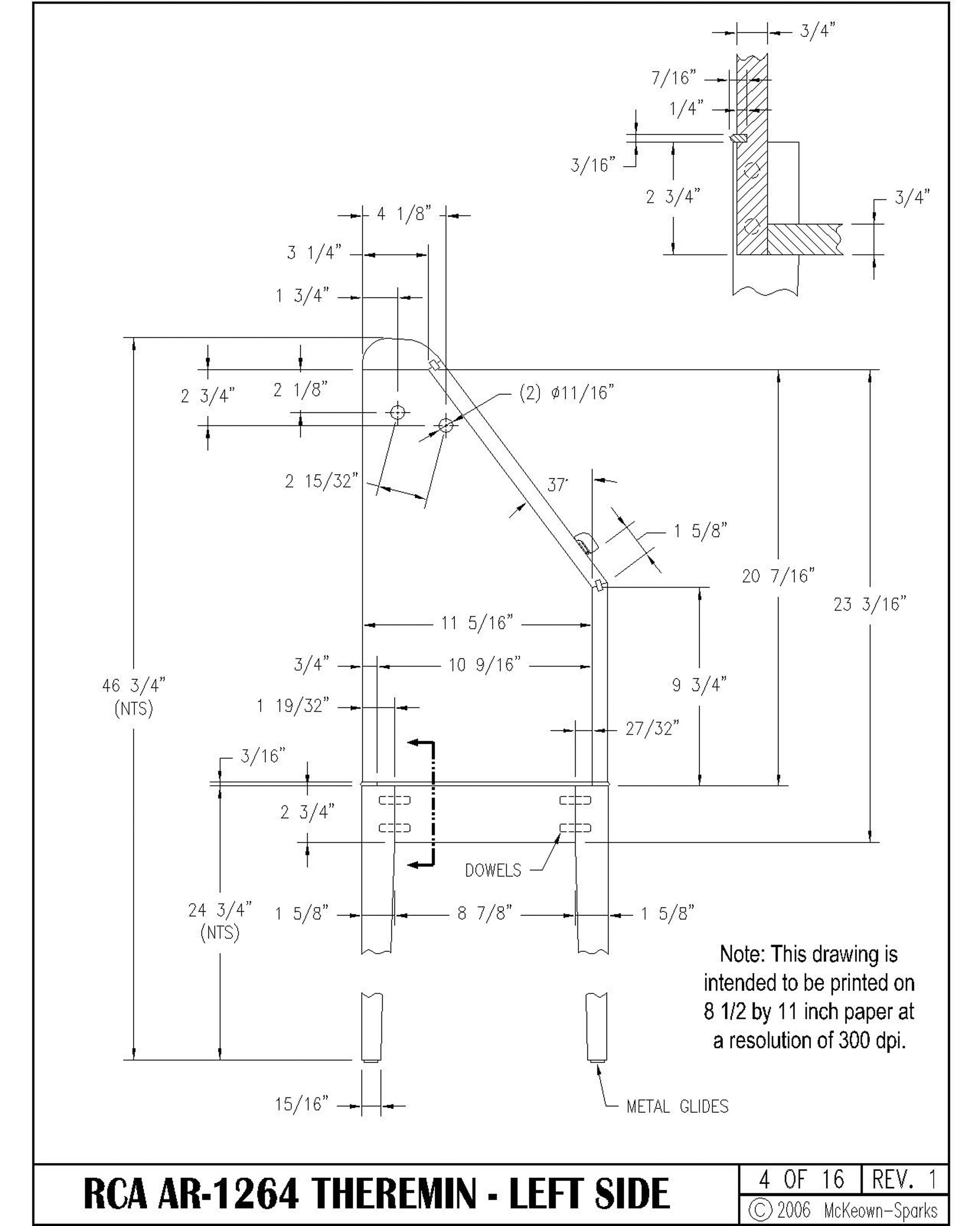
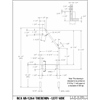
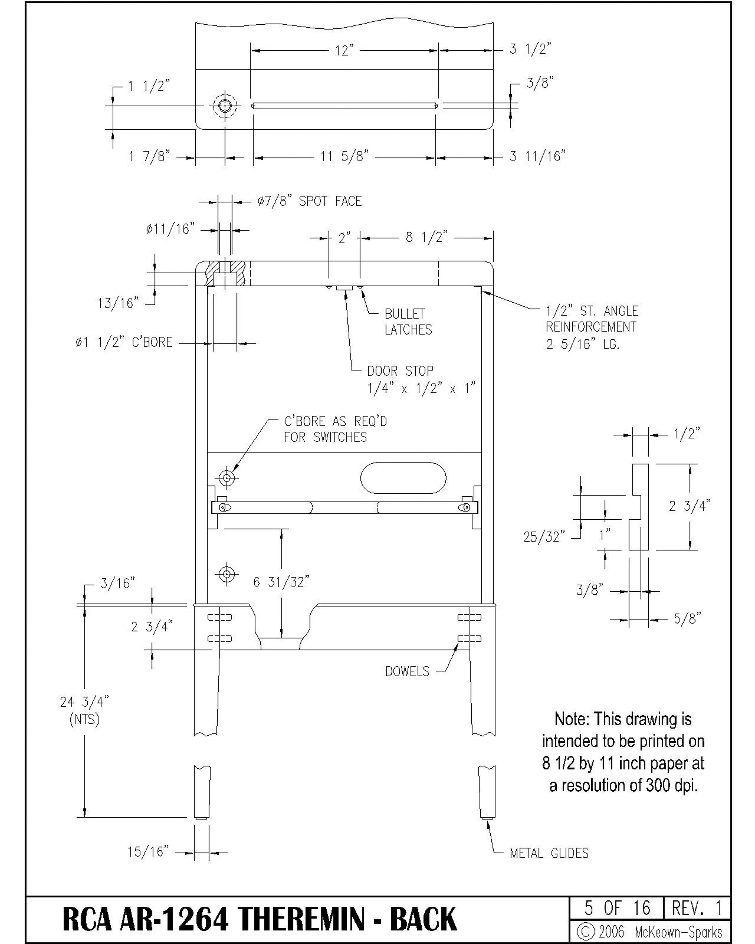
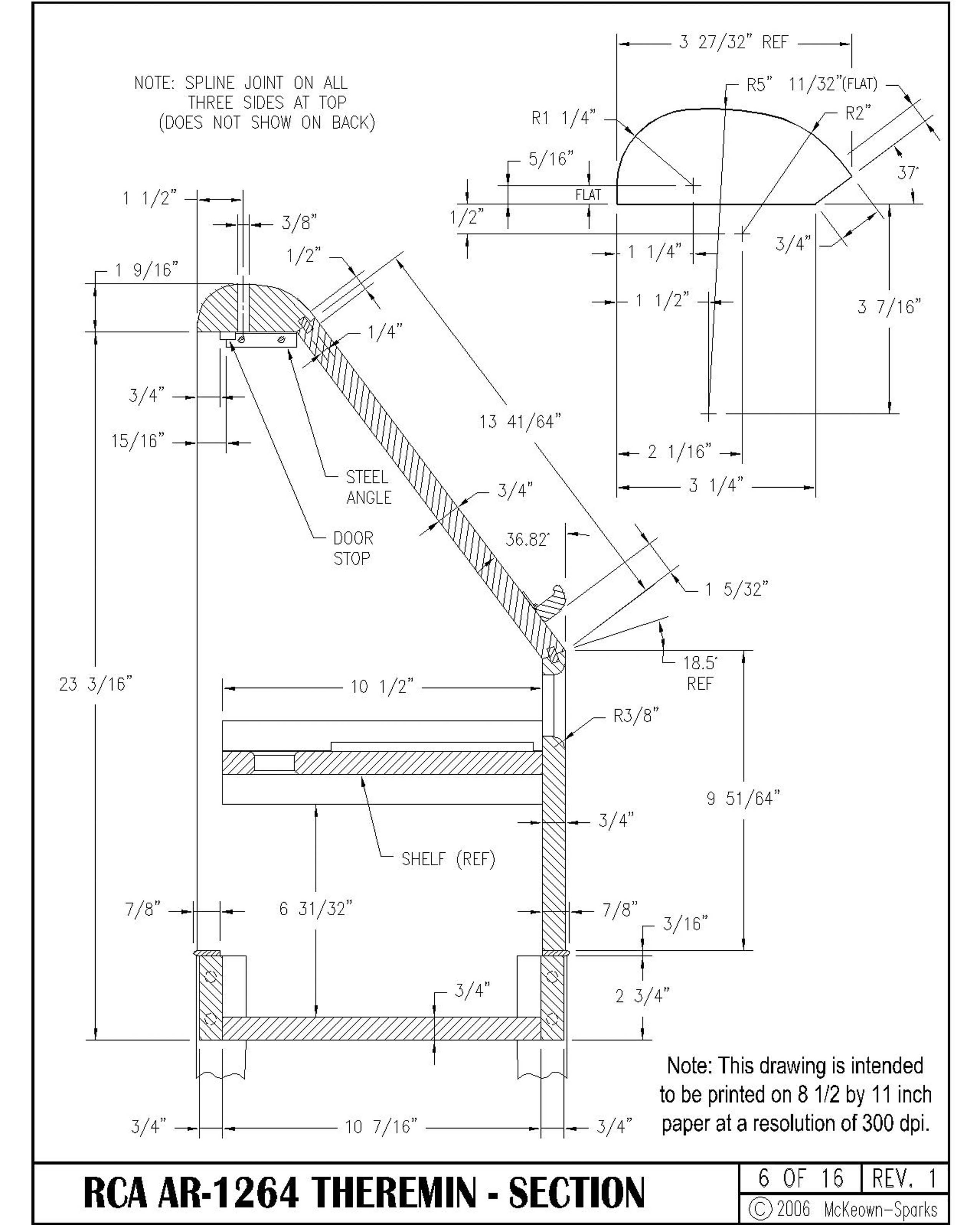
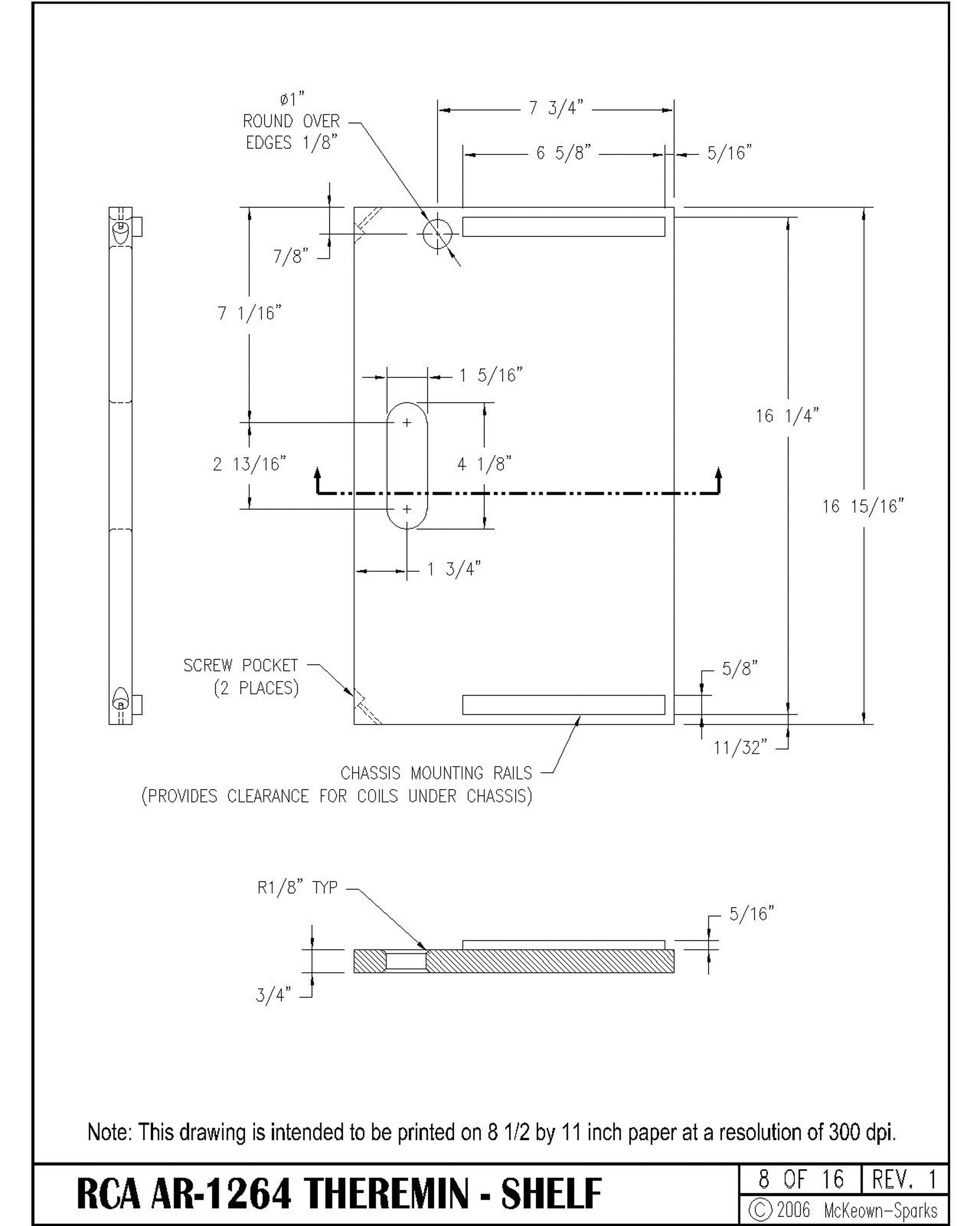
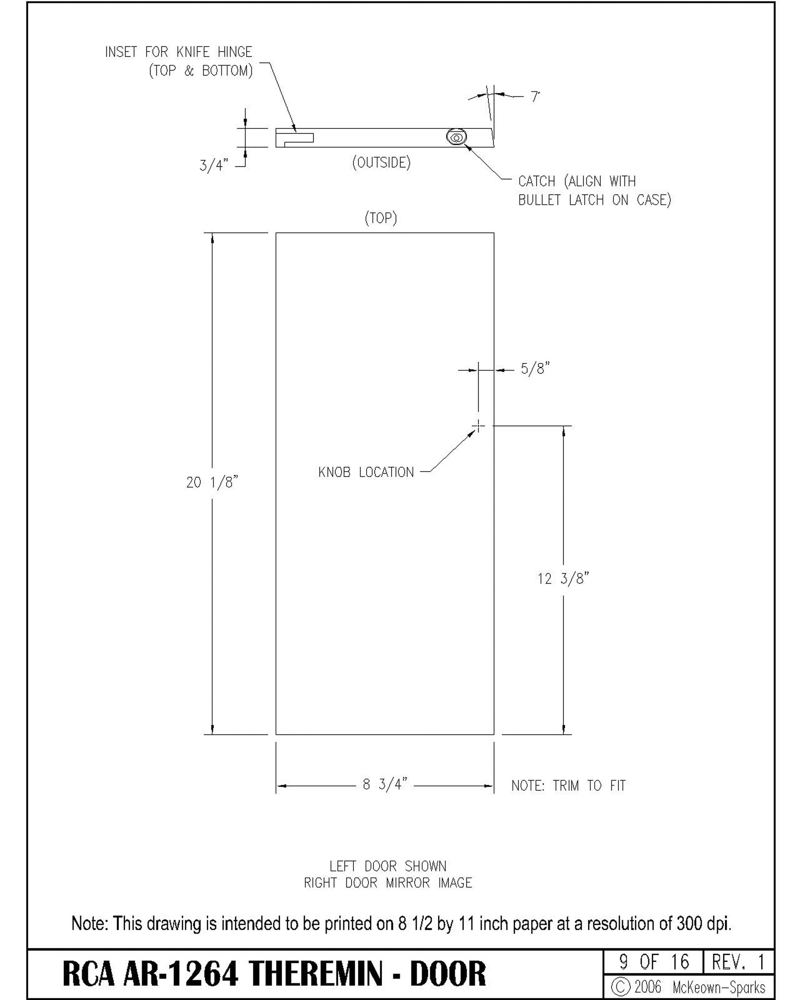
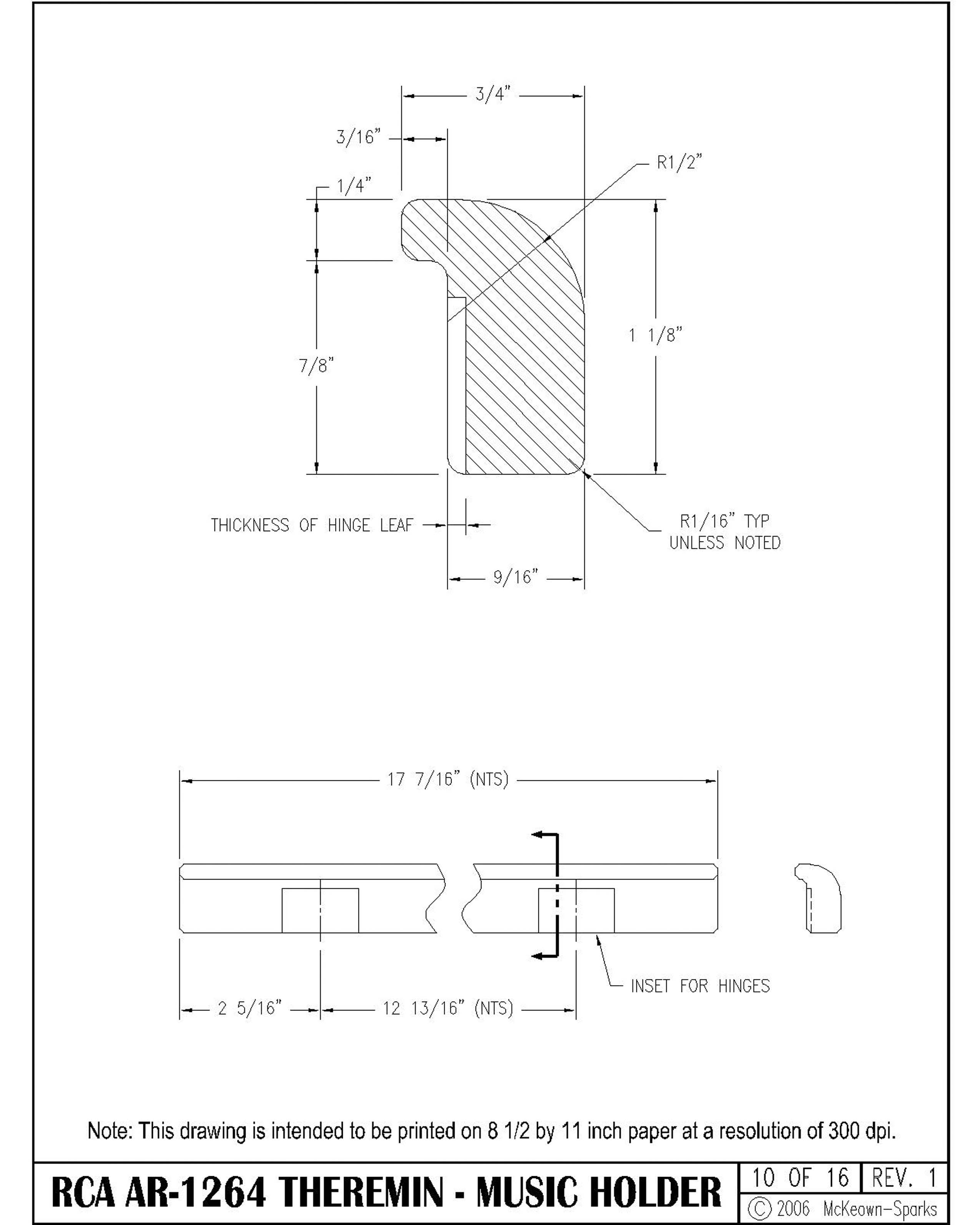
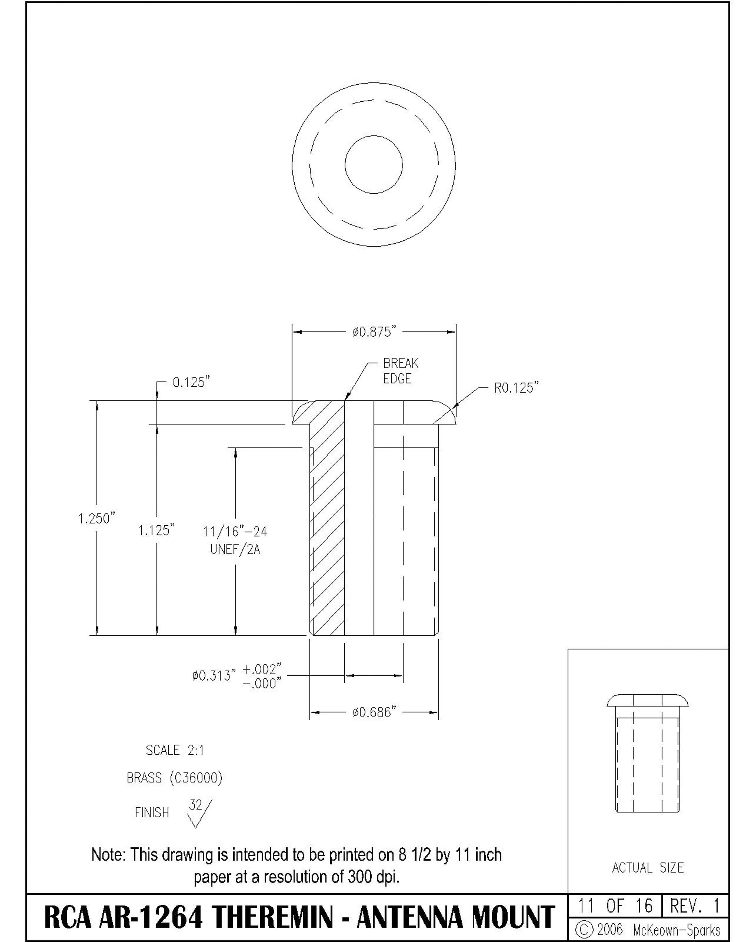
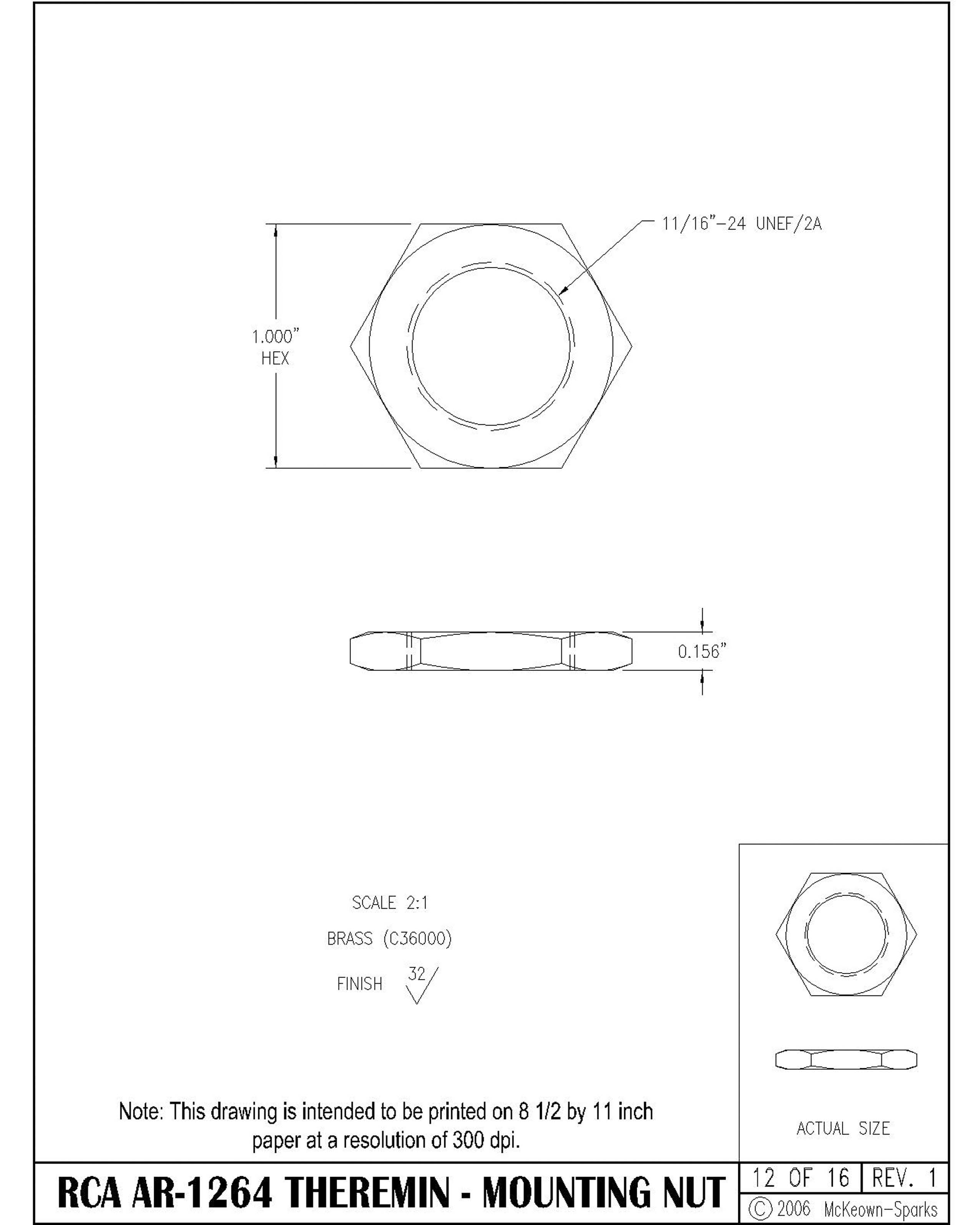
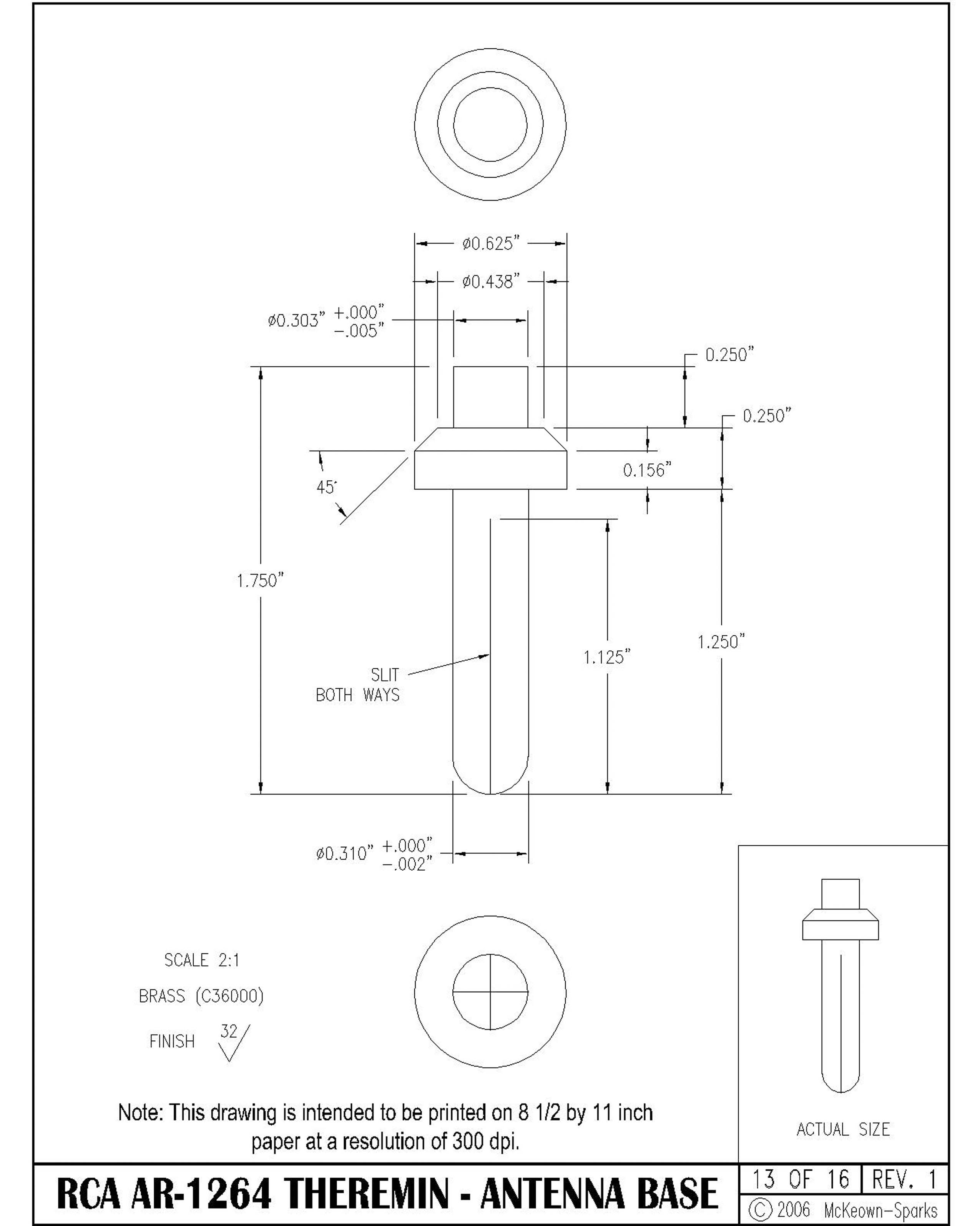
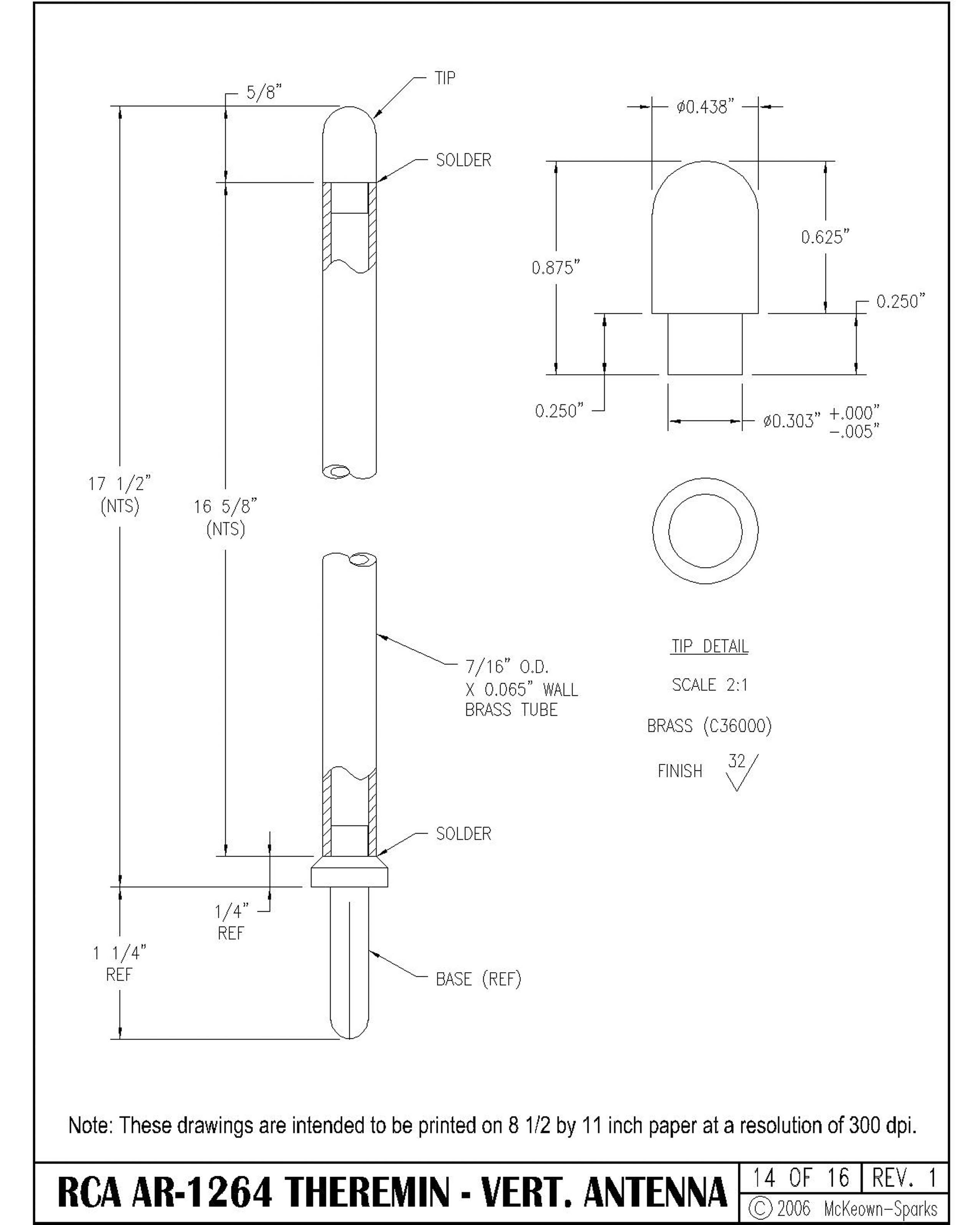
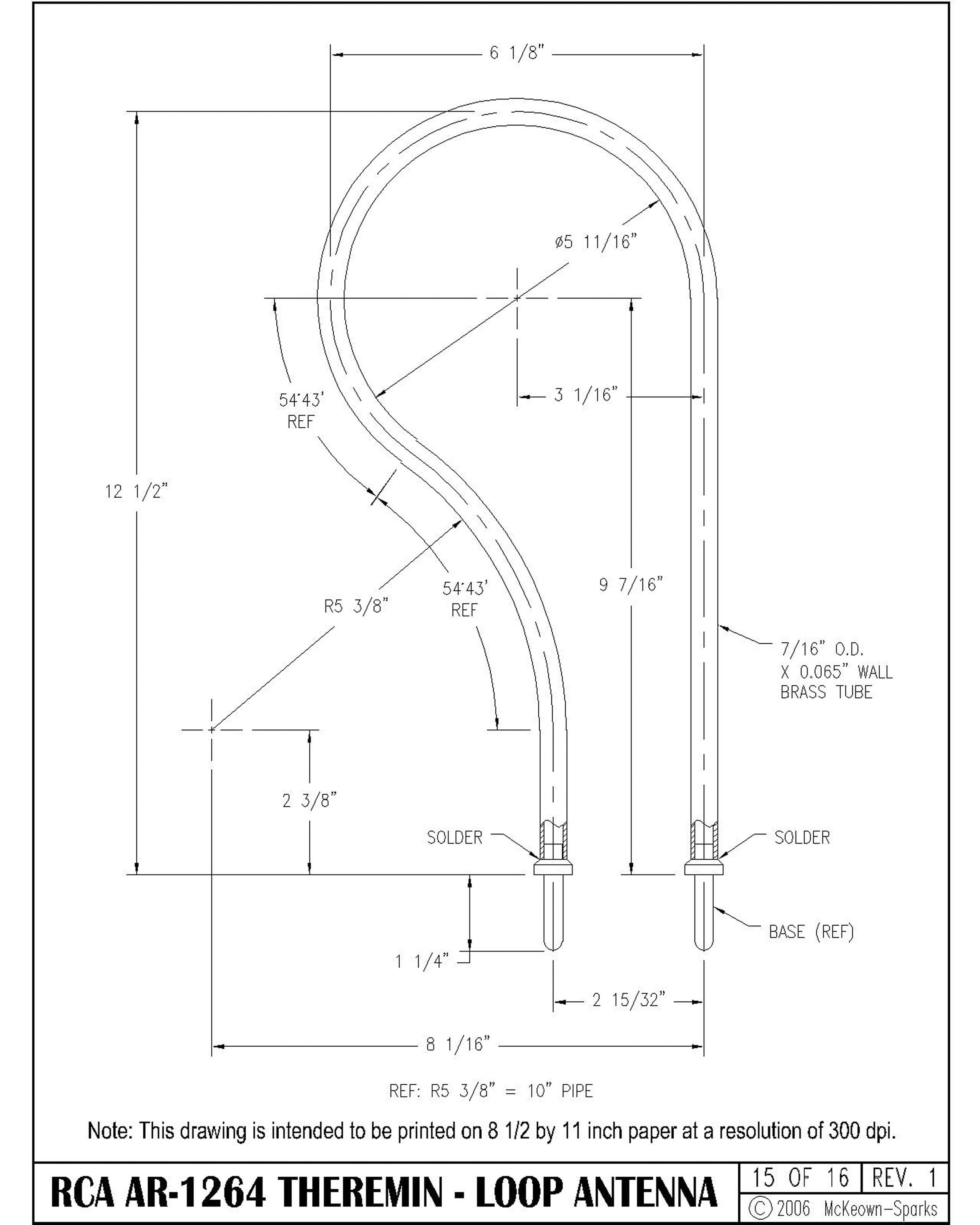
The 16 drawings listed in the appendix are intended to provide enough information for duplicate cabinets to be made or to allow accurate repairs. The following Figures 3 - 6 show typical drawings and consist of the cover, index and two construction drawings. The entire set of 16 drawings can be downloaded as shown in the appendix and are designed to be printed at 300 dpi or more on 8 1/2 by 11 inch paper for proper legibility and scale.
 |
 |
 |
 |
Conclusions
Having built a replica RCA Theremin from scratch and also having restored an original RCA Theremin provided me with first hand knowledge of what was known about the instrument and what would be needed to build a replica. I hope that this information inspires construction of lots of Theremins and cabinets. If you have any questions about this article or restoration questions, feel free to contact me at mmckeown@hughes.net.
Appendix
- Schematic - Power Supply
- Schematic - Theremin
- Drawing 1. Cover Page and Notes
- Drawing 2. Index of Drawings
- Drawing 3. Front
- Drawing 4. Left Side
- Drawing 5. Back
- Drawing 6. Section
- Drawing 7. Bottom
- Drawing 8. Shelf
- Drawing 9. Door
- Drawing 10. Music Holder
- Drawing 11. Antenna Mounting
- Drawing 12. Mounting Nut
- Drawing 13. Antenna Base
- Drawing 14. Vertical (Pitch) Antenna
- Drawing 15. Loop (Volume) Antenna
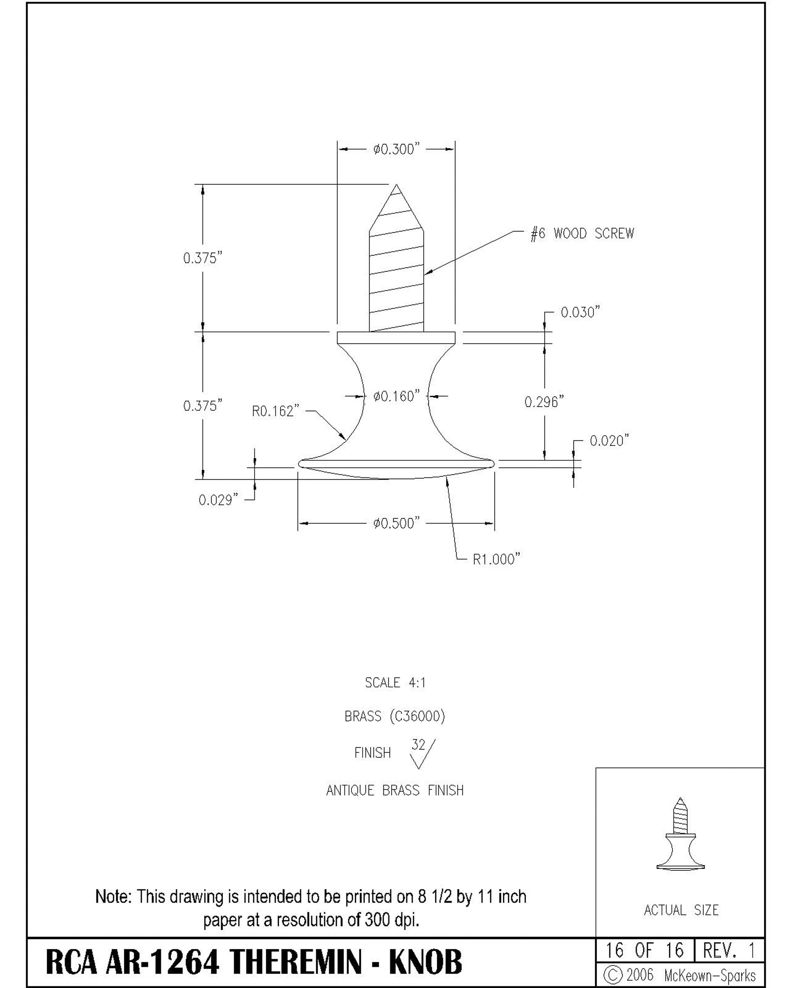
- Drawing 16. Knob
Copyright © by Mark McKeown, 2006


