Teensy 4.0 600MHz ARM Cortex M-7 MCU - ideal for digital MCU based theremin?

Posted: 9/19/2020 1:17:27 PM
dewster

From: Northern NJ, USA

Joined: 2/17/2012

"It was a data cache of CPU."  - Buggins

I kinda loathe caching, particularly in a real-time type processor.  It lets the memory designer, processor designer - everyone but the programmer off the latency hook.  Hello deep pipeline stalls, wildly indeterminate run-times, snoopable speculative execution, and billions of transistors.

"Collect sample data to evaluate oscillator stability and noise level of sensor."

Have you tried high-pass filtering (4th order, 10Hz or so) the data and sending it out the audio port at 48 kHz?  Then use audio tools to capture and analyze the data.   That's how I characterize the noise levels in my system and it really works great.

Posted: 9/19/2020 2:54:11 PM
Buggins

From: Porto, Portugal

Joined: 3/16/2017

"It was a data cache of CPU."  - Buggins

I kinda loathe caching, particularly in a real-time type processor.  It lets the memory designer, processor designer - everyone but the programmer off the latency hook.  Hello deep pipeline stalls, wildly indeterminate run-times, snoopable speculative execution, and billions of transistors.

Fortunately, half (512K) of SRAM inside iMXRT1060 MCU is tightly coupled - dual 64-bit port with simultaneous access for instruction fetch and data read/write. So, if both data and program are located here, no cache is being used. For integer instructions, ~1.5 instructions per clock cycle are being executed. This part of RAM is fast, but not accessible by DMA.

It was surprise for me that second half of RAM (which can be used for DMA ops) is accessed via cache.


"Collect sample data to evaluate oscillator stability and noise level of sensor."

Have you tried high-pass filtering (4th order, 10Hz or so) the data and sending it out the audio port at 48 kHz?  Then use audio tools to capture and analyze the data.  That's how I characterize the noise levels in my system and it really works great.

I've mostly finished software part of sensor.
Frontend - 16-bit timer counter captured on both raising and falling edges - written by DMA to circular buffer.
Each audio frame interrupt (1-3ms depending on frame size), values collected in buffer should be processed by filters.
For 750KHz signal for 1ms there are 1500 captured values to process.
Processing:
each pair of sequential 16-bit values is converted to increments (buf[i+1]-buf[i])
increments are being accumulated in 32bit value and written to another, 32-bit, ring buffer of moving average filter
moving average filter is simple - subtract new value from one delayed by K: (new_value - value[-K]) -- gives log2(K) bits
two sequential outputs of moving average should be averaged (added) - to eliminate signal duty cycle deviations (additinal moving average with window size = 2)
several (3..5) stages of IIR filter with power of 2 K (right shift).

Tested filter performance - on 800MHz MCU, processing of 1ms of ~650KHz signal (~1200 captured samples) takes ~120microseconds.
For two identical filters for pitch and volume it will consume ~25% for sensor data filtering.

At ~2MHz CPU load will be close to 100%

Some optimization can be made (or even some part written in asm) to reduce CPU load.
But anyway, I 10-20% of CPU time is an acceptable price for simple schematics.

I've almost finished code to collect data from real oscillator.
Oscillator period filtered value for 20 seconds with 1ms interval (output of IIR filter) will be collected into array.
Then, it will be printed to serial console and saved to text file.
I hope to use Excel to look at it, try to add linearization formula.
Noise should be visible on plot.

Posted: 9/19/2020 3:45:16 PM
dewster

From: Northern NJ, USA

Joined: 2/17/2012

"It was surprise for me that second half of RAM (which can be used for DMA ops) is accessed via cache."  - Buggins

IMO processors are overly complex, which leads directly to them being insufficiently documented.

"I hope to use Excel to look at it, try to add linearization formula.  Noise should be visible on plot."

There was stuff I only caught by watching a live FFT of the HP axis value output to audio.  The 12Hz LCD update was one (killed by only updating the LCD as necessary), and the "traveling hump" of the audio processing itself was another (killed by dynamically lowering axis processing LPF with pitch).

Posted: 9/19/2020 7:42:28 PM
Buggins

From: Porto, Portugal

Joined: 3/16/2017

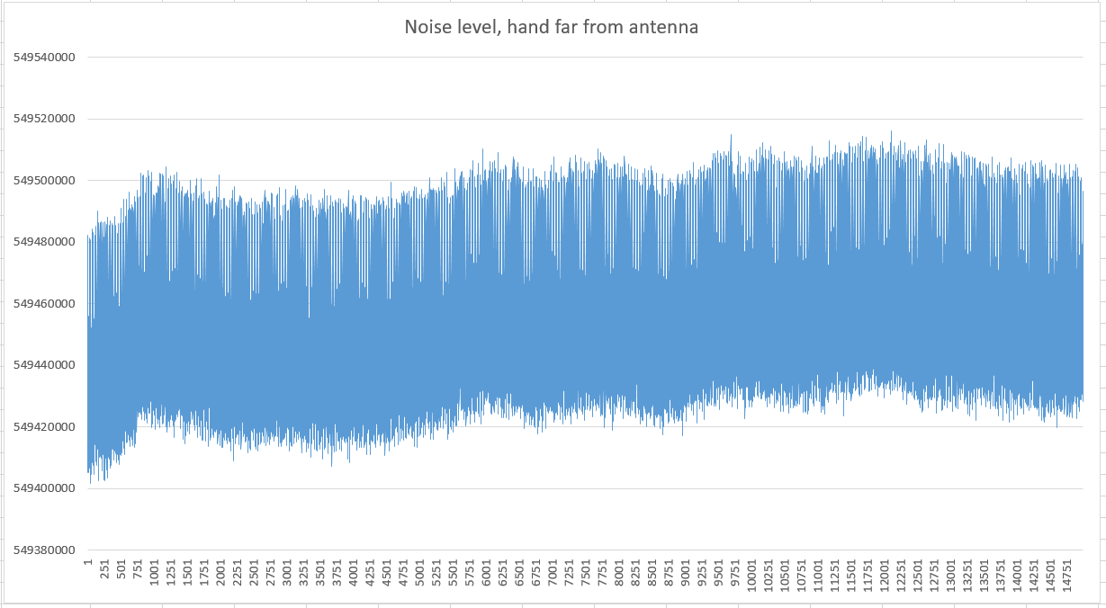
First experimental data captured from teensy4 theremin sensor.
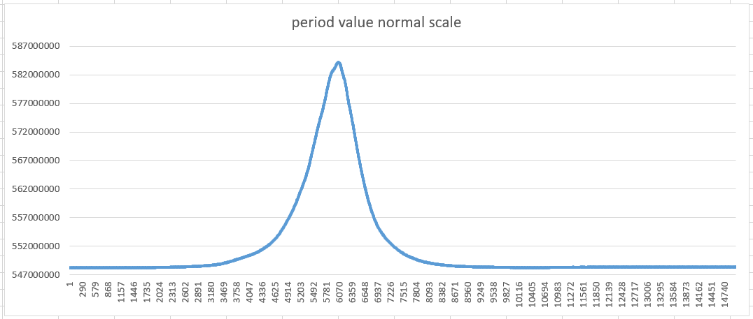
Data is captured for 15 seconds, one signal period measure per 1ms - 15000 values.
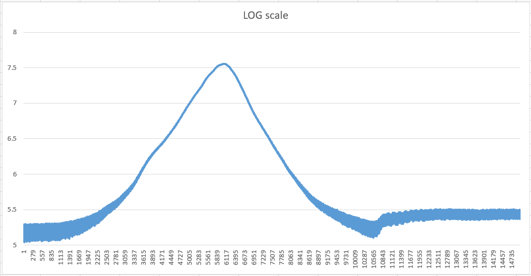
Good news: teensy4 is able to measure oscillator frequency good enough. Taking log() gives almost linear hand position information.
Bad news: oscillator signal is a noisy crap. Both inverter and npn oscillators give similar results.

Spreadsheet with captured data is available here.

Page 1 - just a noise with body far from antenna.
Page 2 - inverter oscillator, hand moves to antenna then back with constant speed, then trying vibrato at 50cm from antenna.
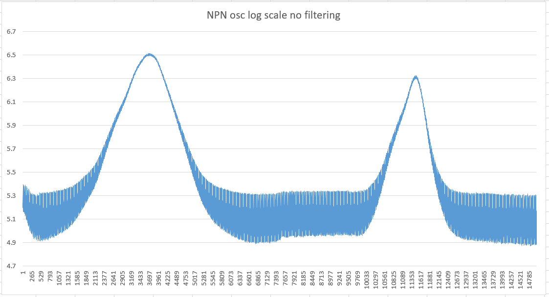
Pages 3, 4 - trying another - NPN - oscillator results.


Charts from page 2:

Plot of raw signal period data:


Converting to log scale. A lot of noise.

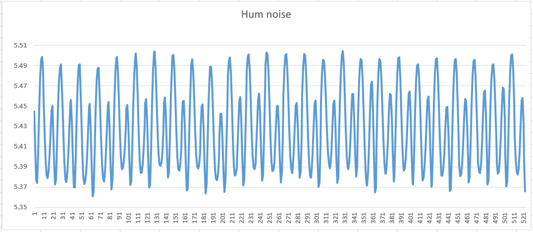
Zooming in: main hum noise is visible w/o any FFT. Noise is periodic with 20ms period (50Hz).
It's not a clean sine. Looks like it has big second harmonic.


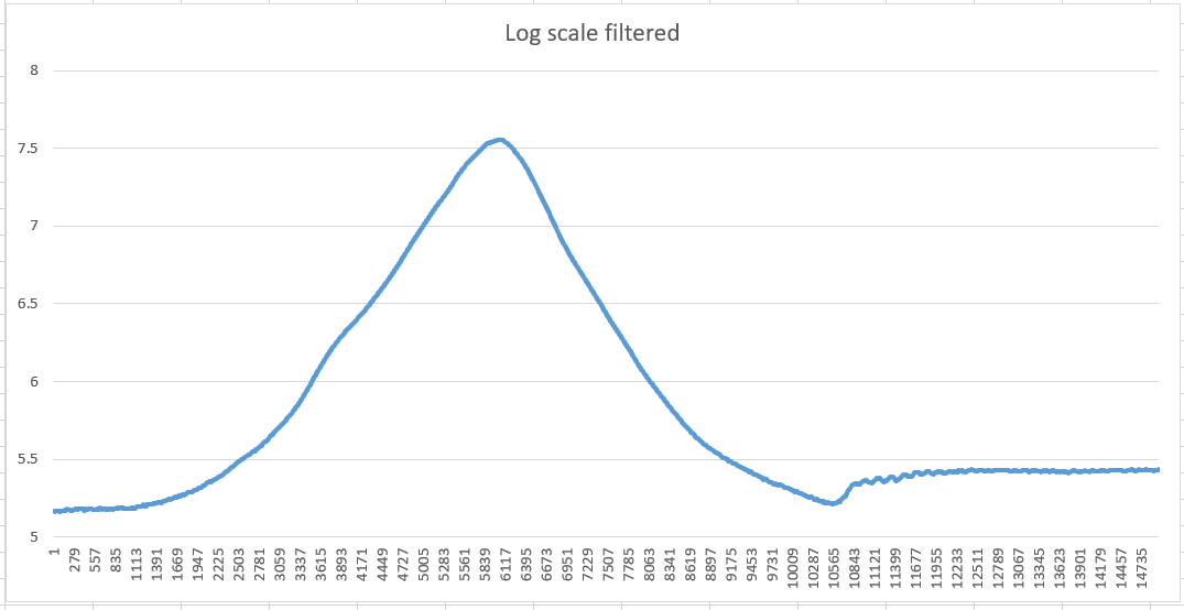
Trying to filter log scale data using simple moving average filter with window length = 20ms

Now vibrato part becomes visible.

Averaging using window length = main hum noise period reduces noise a lot, but adds 10ms (half of main hum period) latency.
Is better main hum filtering approach possible?


Posted: 9/19/2020 8:17:12 PM
dewster

From: Northern NJ, USA

Joined: 2/17/2012

"Bad news: oscillator signal is a noisy crap. Both inverter and npn oscillators give similar results."  - Buggins

Well, there's a huge difference between your oscillator picking up mains hum (which can be filtered out) and it being randomly noisy, jumpy, unstable, or excessively drifty (which can't be filtered out).

"Is better main hum filtering approach possible?"

I use 2nd order state variable notch filters at the first 6 mains harmonics, preceded by a 4th order lowpass at the 5th harmonic, and for lower pitches I move the lowpass even lower.  Each notch takes 13 cycles, and the LP takes 22 cycles, sampling at 48kHz.

A comb filter can notch out 50Hz, 150Hz, 250Hz, etc.  A second can notch out 100Hz, 300Hz, 500Hz, etc.  which leaves you with 350Hz, maybe kill that with 4th order LP at 100Hz.  I do think a steep 100Hz LP is fine for playing.

Posted: 9/21/2020 7:11:45 PM
Buggins

From: Porto, Portugal

Joined: 3/16/2017


Well, there's a huge difference between your oscillator picking up mains hum (which can be filtered out) and it being randomly noisy, jumpy, unstable, or excessively drifty (which can't be filtered out).

Thank you! You are absolutely right. I've examined collected test data deeper.

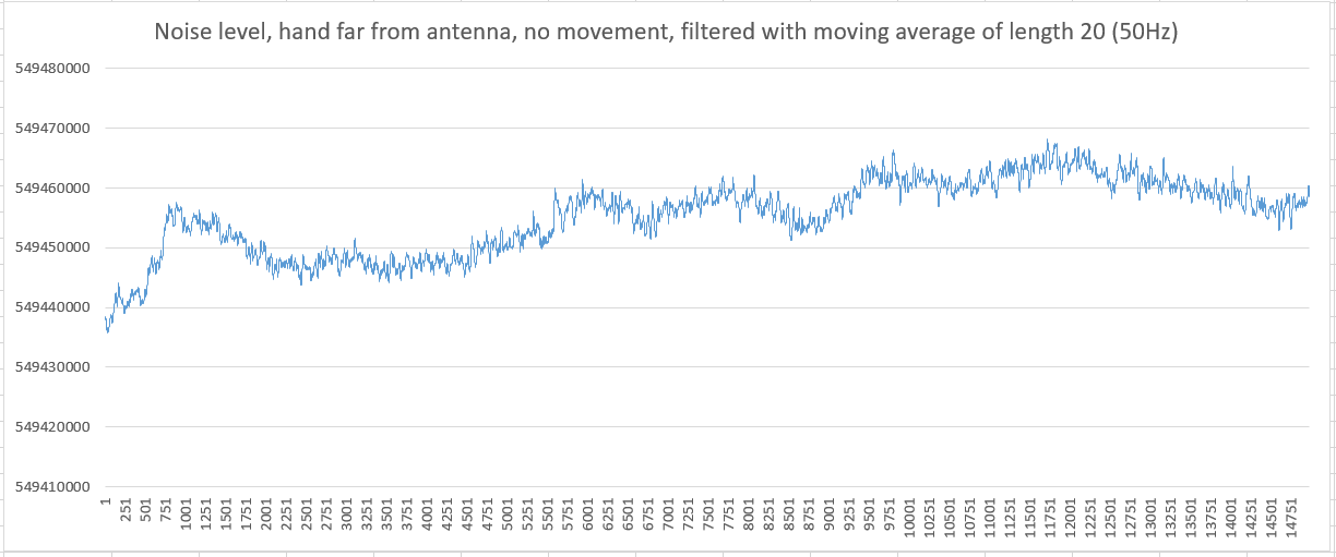
Looking yet another time at first page of spreadsheet with inverter oscillator noise recording, I understood that I see instability.

Added filter (moving average with 20ms interval to filter out 50Hz main hum noise). This is pure instability. I'm sitting 1m from antenna during data capture.

Now let's compare with NPN Collpits oscillator. At first sight, still a lot of noise.

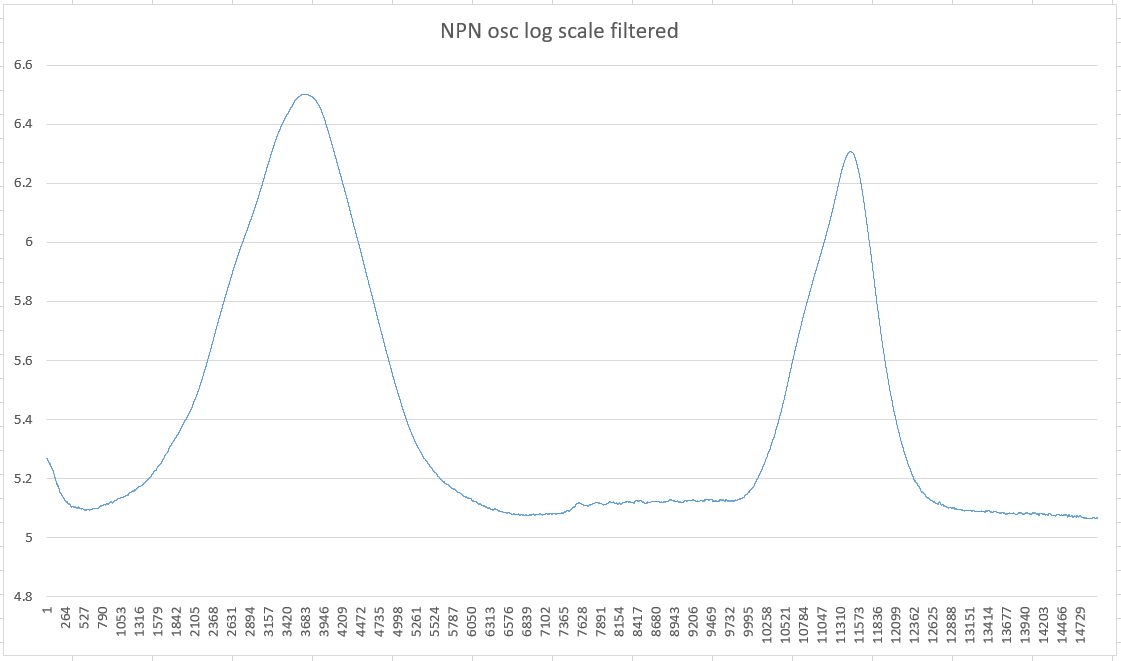
Adding main hum noise filter (20ms moving average) - completely different result.

Hand moved to antenna and back twice. Vibrato between second movement.
For me, it looks playable and linear enough. Vibrato is visible.


So, my inverter based oscillator with its big voltage swing on antenna is a pile of crap. Colpitts rulezz.

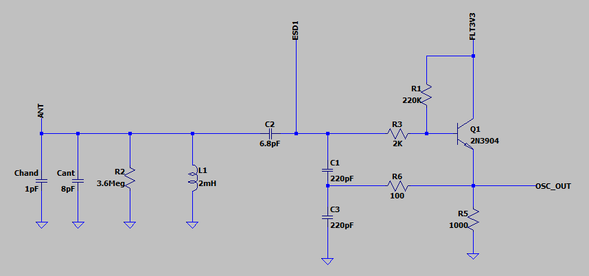
NPN oscillator I used for test is similar to following model (based on one borrowed somewhere from Dewster's thread). When component values are properly tuned, gives ~60Vpp swing on antenna.

I've played with oscillator model. Driving signal is asymmetric. Transistor mostly works half of period.
Can it be improved? Let's take the same oscillator, but on PNP bipolar transistor.
It gives vertically mirrored signal. We can combine two oscillators (NPN+PNP) to achieve something better.
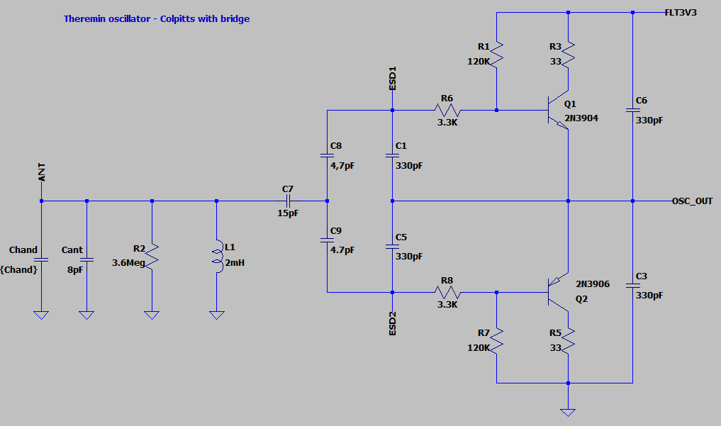
Emitters can be connected together forming bridge.
Output signal is symmetric, antenna swing is 150-220Vpp with 3.3V power supply - twice bigger than single NPN colpitts.
And schematic itself looks nice:


LTSpice model


Posted: 9/21/2020 9:34:36 PM
dewster

From: Northern NJ, USA

Joined: 2/17/2012

"So, my inverter based oscillator with its big voltage swing on antenna is a pile of crap. Colpitts rulezz." - Buggins

I was thinking the CMOS oscillator probably relied too much on the gate input C for phase delay, which could very easily be non-linear, temperature sensitive, etc.  And high gain tends to bring noise along with it.  It's hard to beat simple, low delay, moderate gain oscillators (unless you're doing quadrature DPLL, where the rules are different).

Vadim, you can easily see this noise on a scope with delayed sweep.  Just delay it one mains cycle to cancel that out (equivalent to what you're doing with the moving average sampling set to 20ms), and what remains is oscillator noise.  I use this method extensively when evaluating the oscillators over on my analog thread.  Any instability sticks out like a sore thumb.

"And schematic itself looks nice"

Wow, that is a very nice looking oscillator schematic!  You could call it "symmetric drive" or "push-pull".  I'll have to spice it (thanks for the file)!

You might want to set R2 (RF emission loss?) to 470k or so, I found that helps matching spice sim and reality.  It also helps to reveal oscillators that have starting / running problems.

"Taking log() gives almost linear hand position information."

Take the fractional power of it (negative fractional power of frequency difference) and linearity can be unbelievably good.  From your outstretched arm & hand 1mm away from the antenna to your hand tucked all the way back at your body.

Posted: 9/22/2020 5:33:36 PM
Buggins

From: Porto, Portugal

Joined: 3/16/2017

Vadim, you can easily see this noise on a scope with delayed sweep. Just delay it one mains cycle to cancel that out (equivalent to what you're doing with the moving average sampling set to 20ms), and what remains is oscillator noise. I use this method extensively when evaluating the oscillators over on my analog thread. Any instability sticks out like a sore thumb.

Unfortunately, I don't have good scope.


Take the fractional power of it (negative fractional power of frequency difference) and linearity can be unbelievably good.

Cannot understand your proposal. Could you please provide sample formula?

BTW, I've used log(T - (T_max + e)) where T is measured oscillator period and T_max+e is period for far hand distance (infinity).
In this case, linearity on near and medium distance looks good, but I'm unsure about far distances.


You might want to set R2 (RF emission loss?) to 470k or so, I found that helps matching spice sim and reality.  It also helps to reveal oscillators that have starting / running problems.


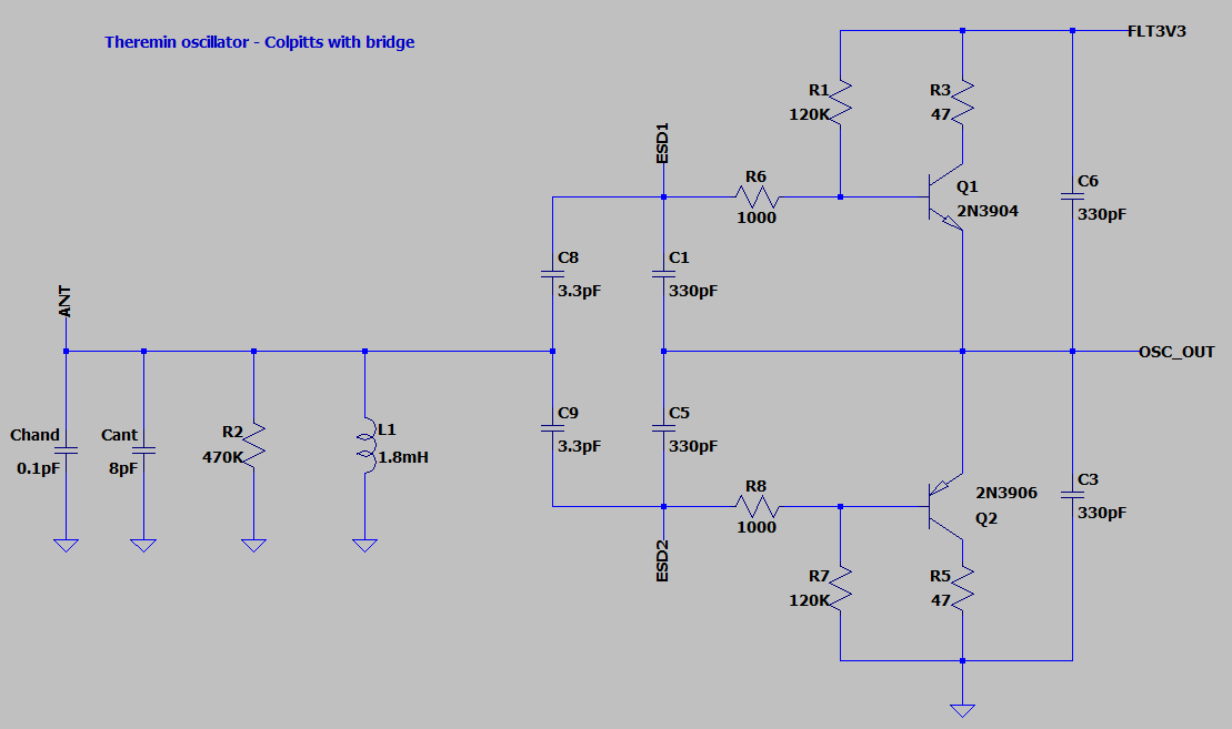
Played with oscillator model. Trying to optimize for different L and different energy loss. Criteria: maximize antenna swing, minimize oscillation startup time, keeping sensitivity (frequency change on C_hand).
Worst case 40Vpp on antenna (470K energy loss resistor). Up to 200Vpp when energy loss is small and L wire has smaller R.

Updated schematic:

Updated LTSpice model link

Going to design PCB in KiCAD and order PCB manufacturing.

Are there any transistors better than 2n3904/06? Does it make sense to search for them?

What is suitable power filter for oscillator PCB?
I'm planning to use simple RC on 3.3V input on oscillator board: small R (10) and big C (1-2uF).
Is it enough?

Posted: 9/22/2020 5:58:59 PM
dewster

From: Northern NJ, USA

Joined: 2/17/2012

"Are there any transistors better than 2n3904/06? Does it make sense to search for them?"  - Buggins

Good question, though I don't know the answer.  IIRC Bob Moog used driver / power transistors in the EW Pro, I assume for drift?  Perhaps also for noise?  Though his oscillators can probably suck some current at times.

"What is suitable power filter for oscillator PCB?"

The absolute best filter is an LDO 3.3V regulator on the board dropping 5V (I use LP2950).  You have to worry a bit about power cycling, but you probably want a series resistor on the output anyway for signal integrity.

Posted: 9/23/2020 6:34:04 PM
Buggins

From: Porto, Portugal

Joined: 3/16/2017


"Are there any transistors better than 2n3904/06? Does it make sense to search for them?"  - Buggins


Good question, though I don't know the answer.  IIRC Bob Moog used driver / power transistors in the EW Pro, I assume for drift?  Perhaps also for noise?  Though his oscillators can probably suck some current at times.

"What is suitable power filter for oscillator PCB?"


The absolute best filter is an LDO 3.3V regulator on the board dropping 5V (I use LP2950).  You have to worry a bit about power cycling, but you probably want a series resistor on the output anyway for signal integrity.


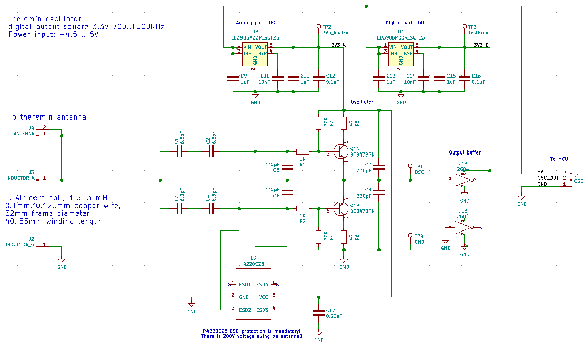
Designed symmetric colpitts oscillator PCB in KiCAD.
Selected components available in local store.
For transistors, I'm using BC847BPN - npn+pnp transistor pair (I hope they match by hFE).
To minimize noise from power line - used two LDO regulators - LD3985M33R - separate for analog and digital (output buffer) parts.


PCB is designed to fit inside 32mm ppl water pipe for pipe monster cabinet design. In this case half of PCB will be located inside coils.

3D render of PCB, top view


bottom view

KiCAD project is available on GitHub

Gerber files link

Going to order manufacturing of these PCBs

UPD: ordered 10pcs - white mask color - on pcbway.com for $4 + delivery $6

You must be logged in to post a reply. Please log in or register for a new account.