"It was a data cache of CPU." - BugginsI kinda loathe caching, particularly in a real-time type processor. It lets the memory designer, processor designer - everyone but the programmer off the latency hook. Hello deep pipeline stalls, wildly indeterminate run-times, snoopable speculative execution, and billions of transistors.
Fortunately, half (512K) of SRAM inside iMXRT1060 MCU is tightly coupled - dual 64-bit port with simultaneous access for instruction fetch and data read/write. So, if both data and program are located here, no cache is being used. For integer instructions, ~1.5 instructions per clock cycle are being executed. This part of RAM is fast, but not accessible by DMA.
It was surprise for me that second half of RAM (which can be used for DMA ops) is accessed via cache.
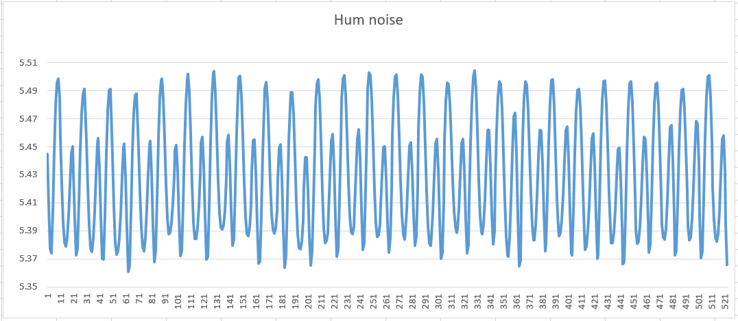
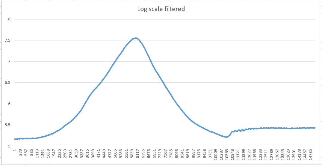
"Collect sample data to evaluate oscillator stability and noise level of sensor."Have you tried high-pass filtering (4th order, 10Hz or so) the data and sending it out the audio port at 48 kHz? Then use audio tools to capture and analyze the data. That's how I characterize the noise levels in my system and it really works great.
I've mostly finished software part of sensor.
Frontend - 16-bit timer counter captured on both raising and falling edges - written by DMA to circular buffer.
Each audio frame interrupt (1-3ms depending on frame size), values collected in buffer should be processed by filters.
For 750KHz signal for 1ms there are 1500 captured values to process.
Processing:
each pair of sequential 16-bit values is converted to increments (buf[i+1]-buf[i])
increments are being accumulated in 32bit value and written to another, 32-bit, ring buffer of moving average filter
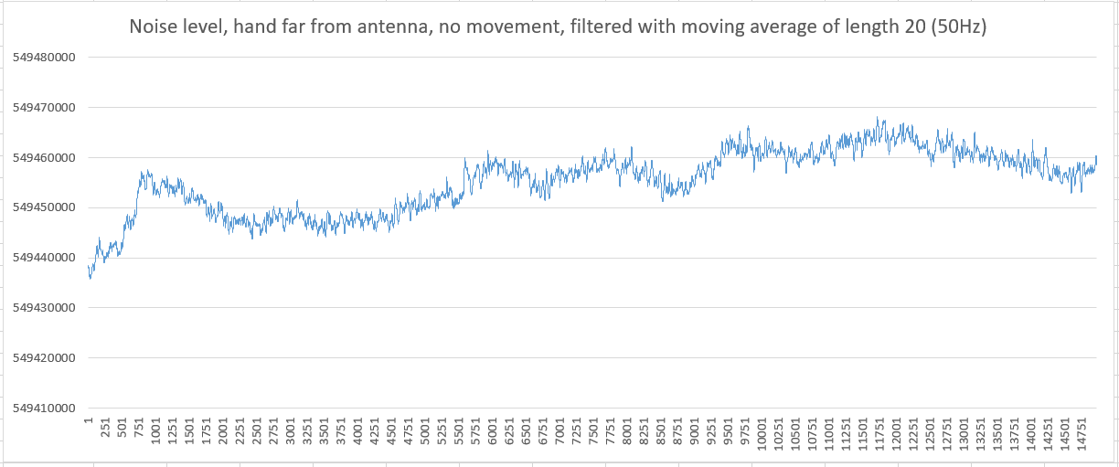
moving average filter is simple - subtract new value from one delayed by K: (new_value - value[-K]) -- gives log2(K) bits
two sequential outputs of moving average should be averaged (added) - to eliminate signal duty cycle deviations (additinal moving average with window size = 2)
several (3..5) stages of IIR filter with power of 2 K (right shift).
Tested filter performance - on 800MHz MCU, processing of 1ms of ~650KHz signal (~1200 captured samples) takes ~120microseconds.
For two identical filters for pitch and volume it will consume ~25% for sensor data filtering.
At ~2MHz CPU load will be close to 100% 
Some optimization can be made (or even some part written in asm) to reduce CPU load.
But anyway, I 10-20% of CPU time is an acceptable price for simple schematics.
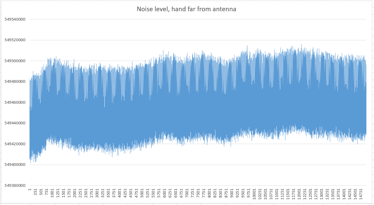
I've almost finished code to collect data from real oscillator.
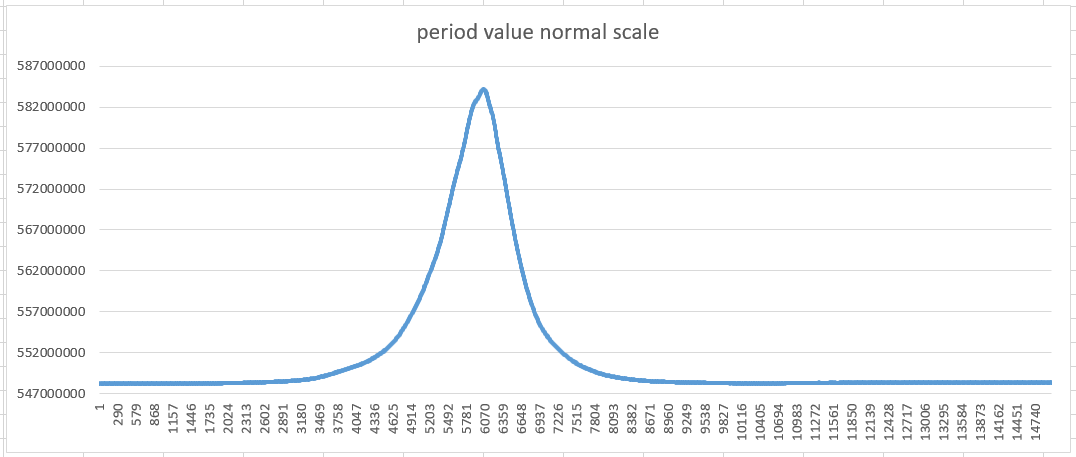
Oscillator period filtered value for 20 seconds with 1ms interval (output of IIR filter) will be collected into array.
Then, it will be printed to serial console and saved to text file.
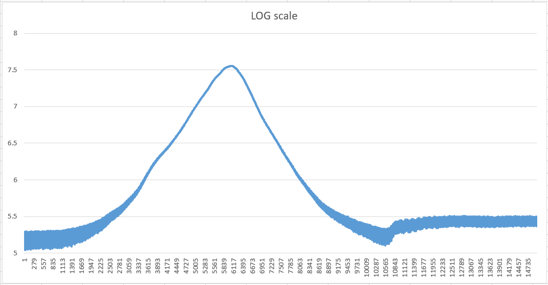
I hope to use Excel to look at it, try to add linearization formula.
Noise should be visible on plot.