Vadim, I've been playing with your interesting oscillator on a breadboard for a couple of hours, and it seems quite nice!
Wow! It's pretty good news. Thank you for trying it in hardware. Unfortunately my one year old son prevents me from soldering and breadboarding experiments.
I don't have 74HCU04 on hand, but I do have 74AHC04, 74HC04, 74LVU04.
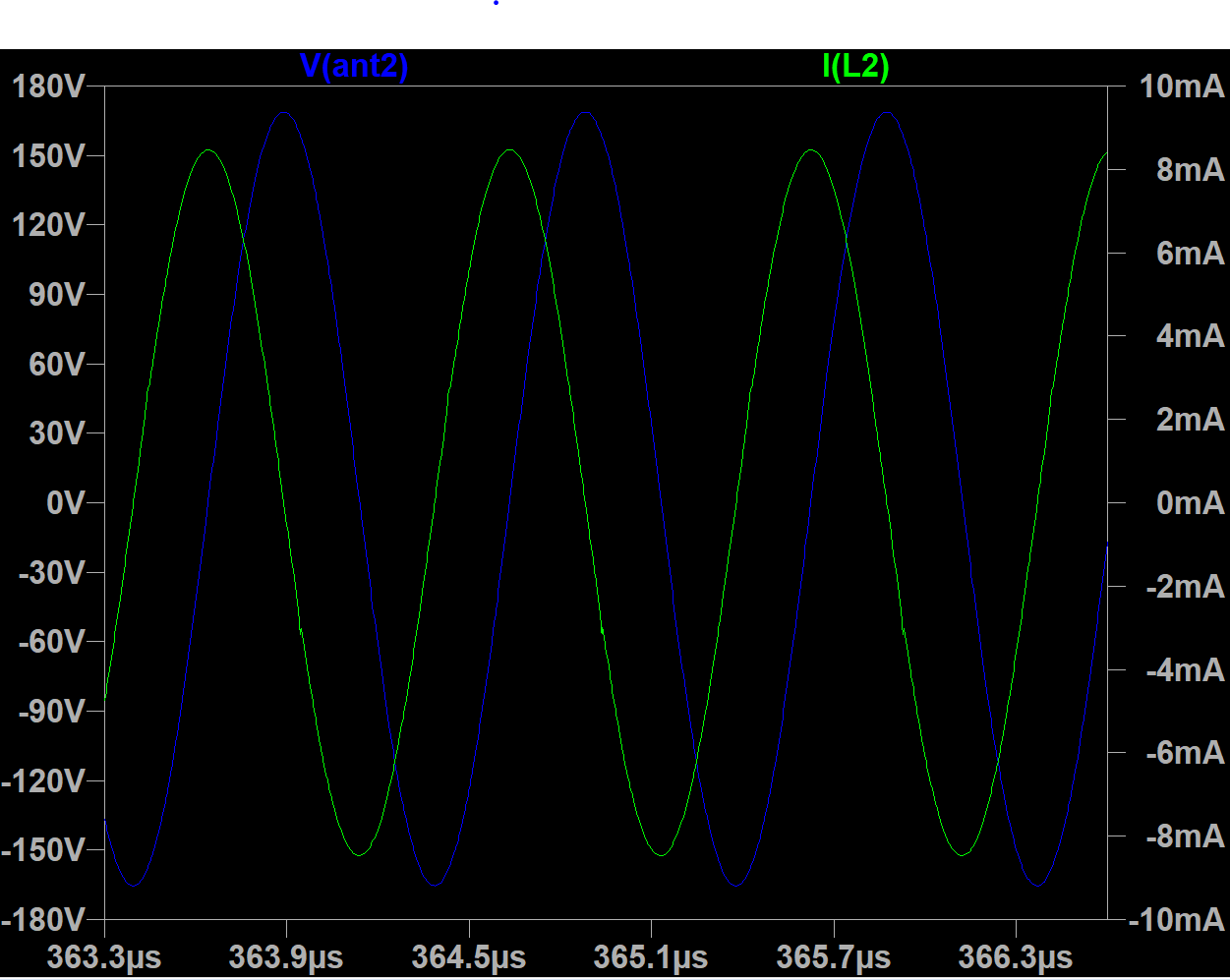
LVU gives very rounded drive with obvious phase error and lower antenna voltage, and doesn't work well with my 0.5mH coil (stalls easily) though the drive duty cycle is 50/50. HC has threshold problems I think, the drive duty cycle is roughly 60/40, though it gives sharp ringing drive and high voltages. AHC seems to work best, with sharp ringing drive, no obvious major phase error, 50/50 drive, and high antenna voltages.
I see 220Vpp with the 0.5mH, 300Vpp with 3.7mH (with a small rod antenna).
Have you really tried buffered inverters? I didn't expect that they would work 
For LVU, you can try changing sensing inverter input cap value - it allows changing of phase. Probably, it's possible to achieve zero phase error by using of proper decoupling capacitor and feedback resistor. I believe, input cap should be tuned for different LC tank frequency.
Does inverter bases current sensor oscillator survive hand touching antenna?
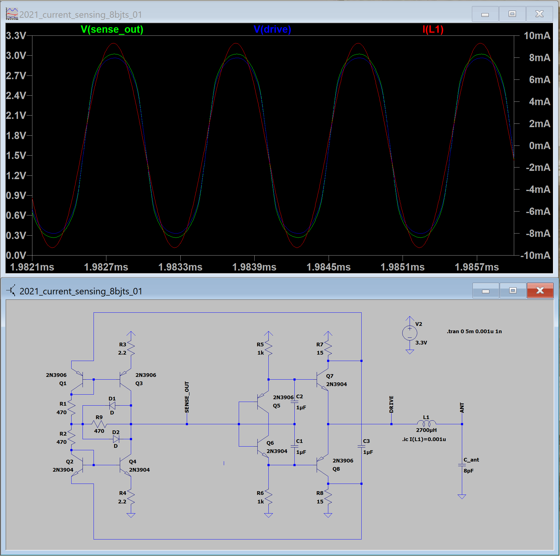
I think it works better than my 8 transistor oscillator, particularly for smaller coils. It gives higher voltage but more importantly it seems more stable, with less jiggling around at 16.666ms (1/60Hz) and less phase noise, though my bench is fairly noisy tonight.
It is fairly immune to supply voltage variation, which to me is always a good sign.
The 8 transistor is even more stable with supply voltage variation, and is harder to stall, but that's about it.
For my testing today I was using all 5 buffers in parallel to drive the coil. I also used 22 ohm resistors to the rails rather than 10, which seemed to help a little with stalling @ finger pinch of the bare antenna rod. A minor consideration is driving external things like processor or FGPA pins.
Using one of the buffers to do this (like you are doing above) is maybe good, but any line disturbance could possibly come back to the oscillator via current to/from the resistored drive rails.
I might use something like the two transistor 4th order LPF here driven from the supply rails to help isolate things, though I haven't actually tested that circuit on the bench yet.
Good point regarding output line noise. Output implementation should be changed.
One more thing that could be an issue is any hysteresis they sometimes build into these parts to help reject digital noise. I think the AHC parts have it, and I keep waiting to get bitten by it on the D-Lev.
I believe only buffered inverters have hysteresis. But oscillators are analog devices, and I believe it's better to use unbuffered inverters there.
Update on my simulation experiments.
Found LVCU04 spice model from NXP. It's working w/o bugs unlike TI one.
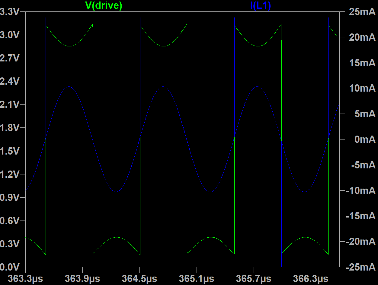
74hcu04 inverter draws 2.5mA in "analog mode" (when input is close to VCC/2).
74lvcu04 inverter draws ~20 times more - 45mA.
When sensing 74lvcu04 is powered in parallel with drive inverter, it causes constant 45mA current through sensing resistors and hence reduces drive voltage swing.
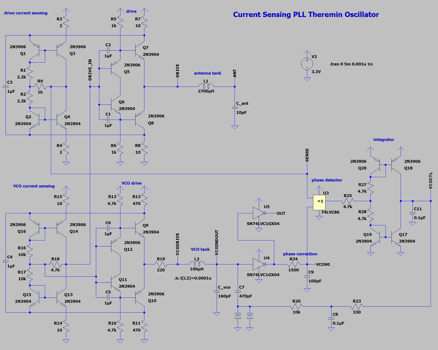
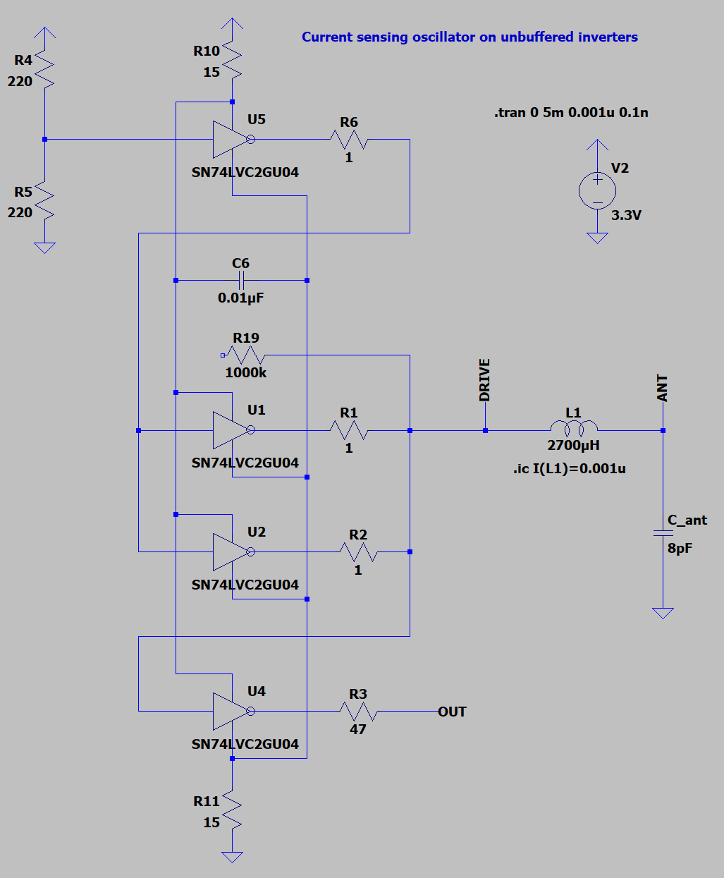
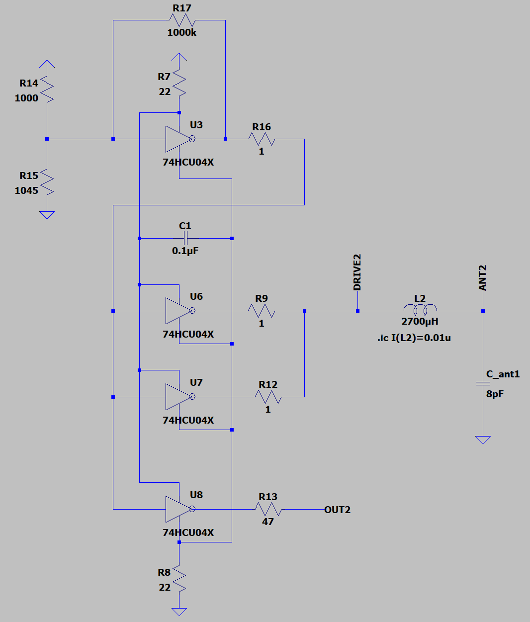
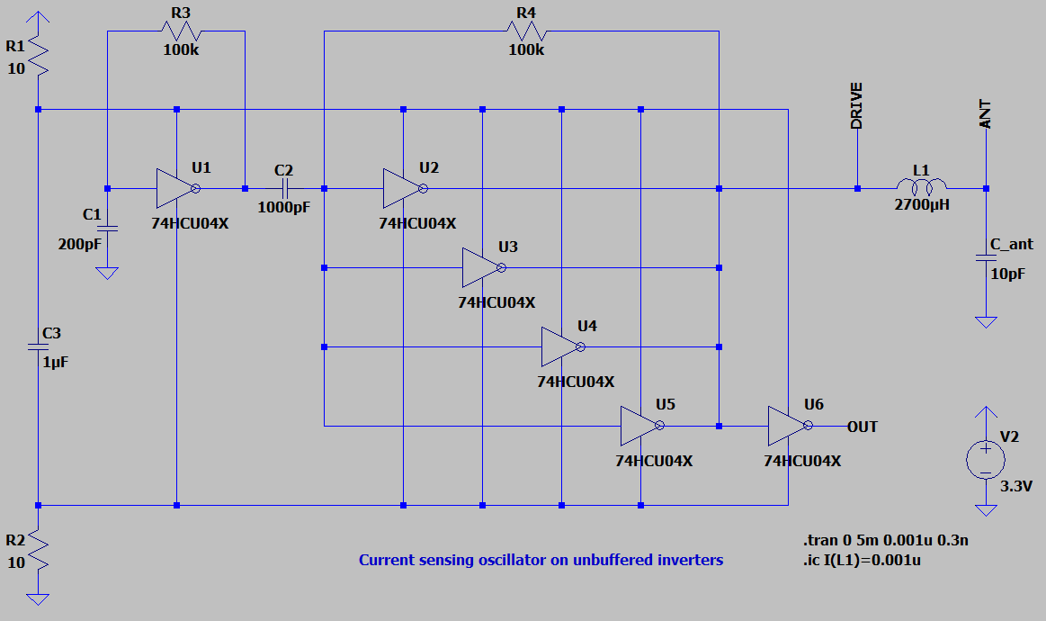
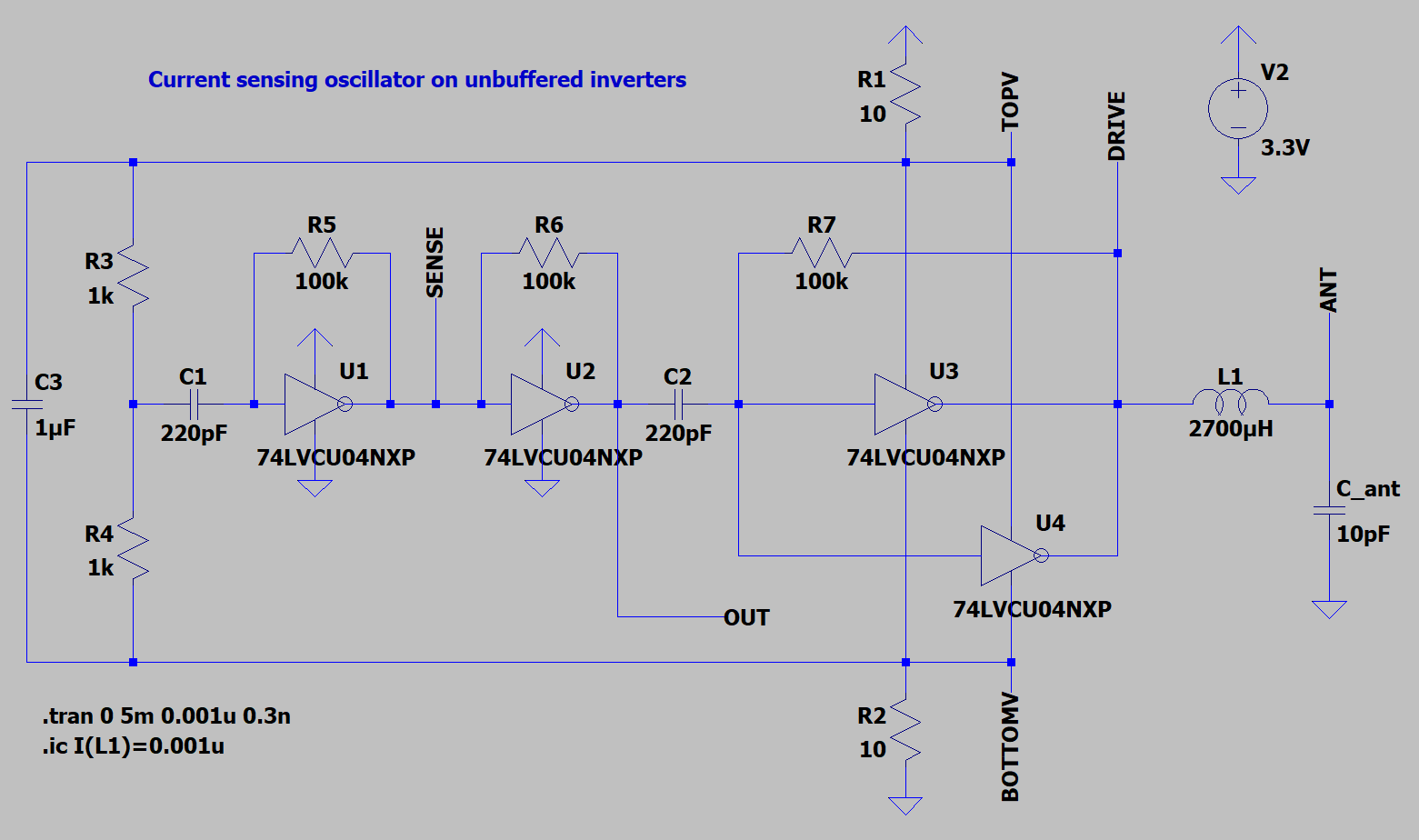
Let's extract sensing inverter - power it directly from power rails, and feed with middle of drive power pins.
Sensing signal becomes inverted, and now requires additional inverter.
Second inverter output looks nice for output source - smooth waveform should cause less ringing in line. Noise from output line now do not go through sensing resistors, and at least is not being amplified by current sensor.
Eric, do you think it's ok to implement output this way? If so, only two 74LVC2GU04 ICs are needed.
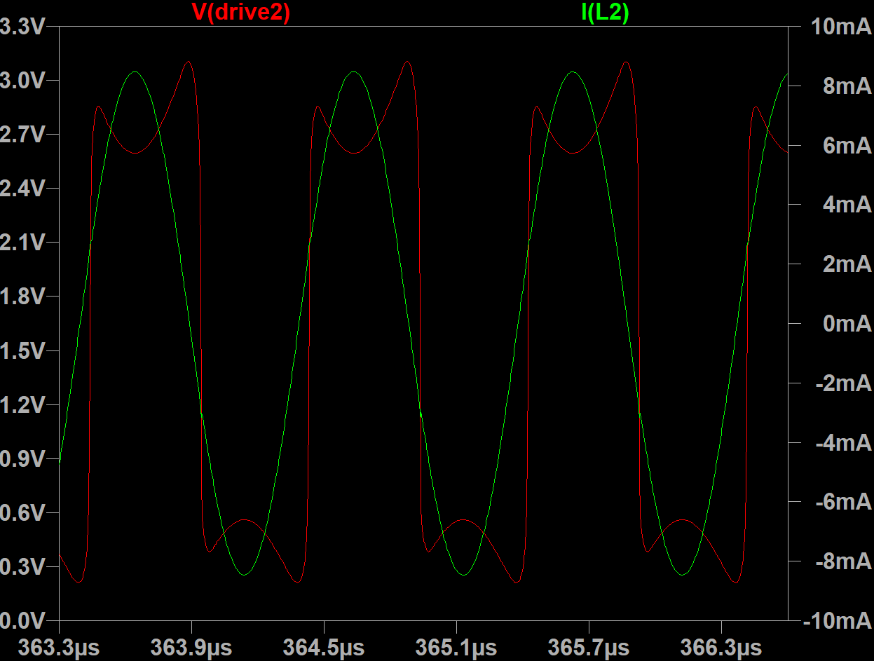
Phase error still may be corrected by changing of sensing inverter input decoupling capacitor.
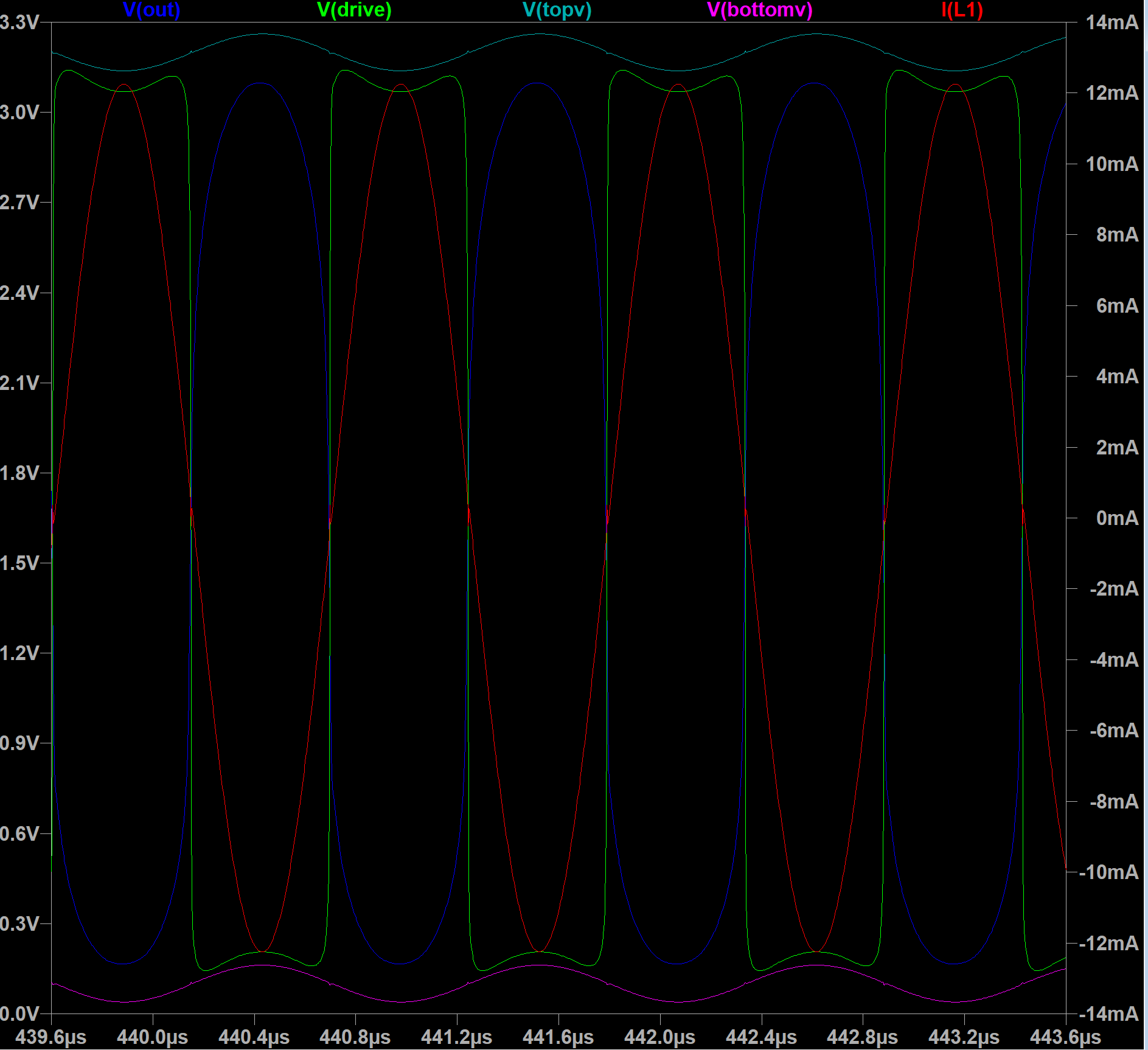
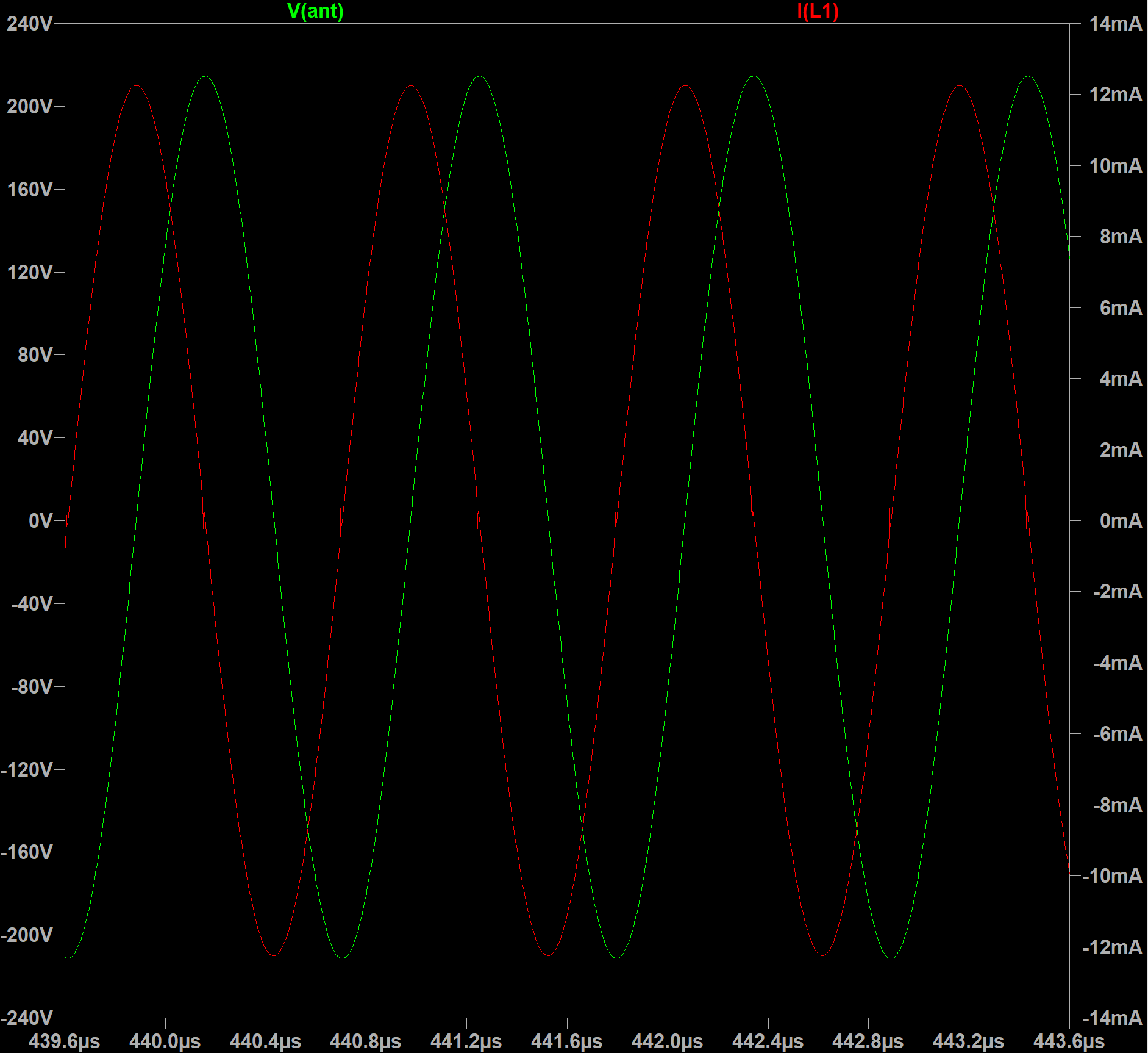
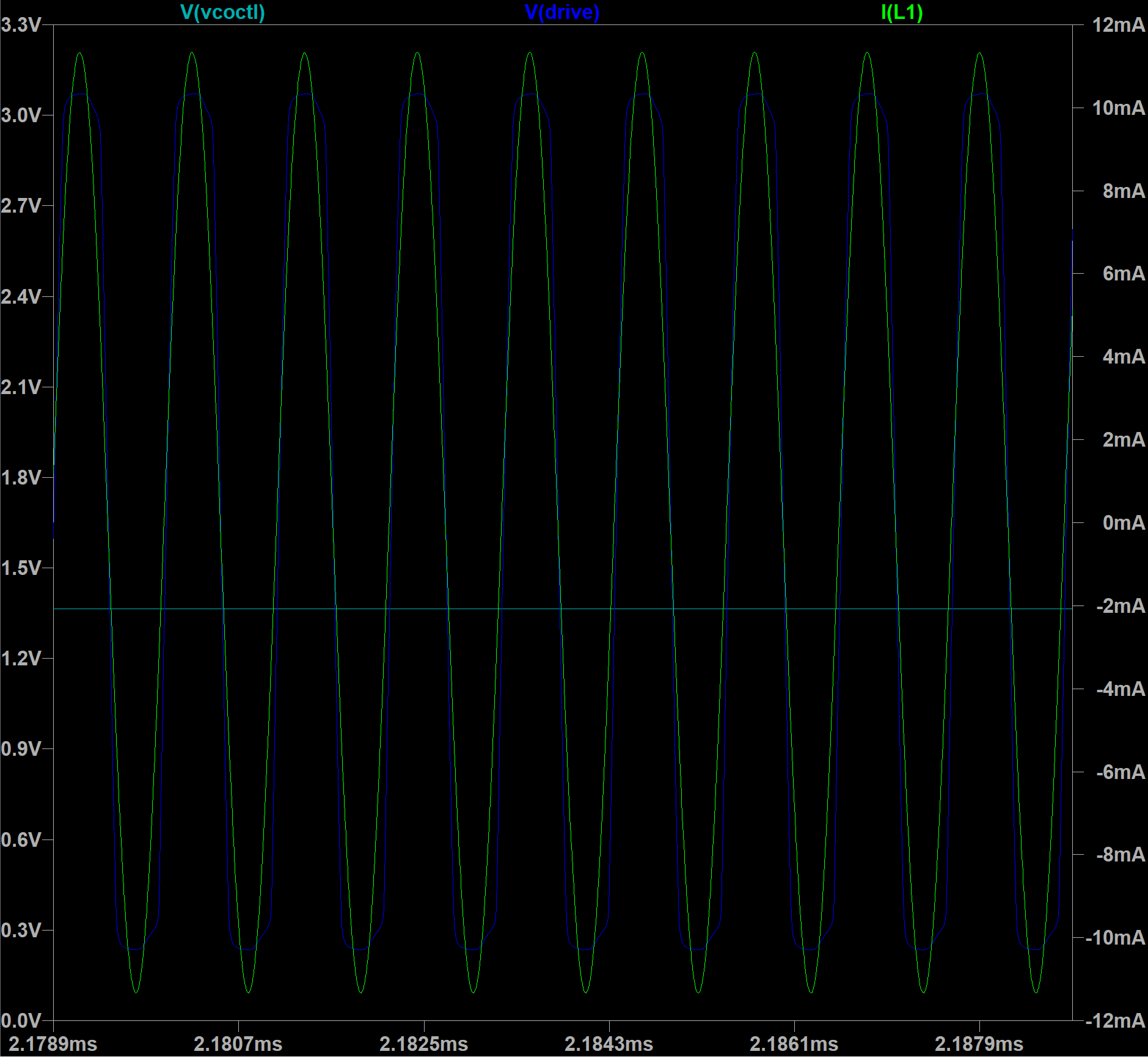
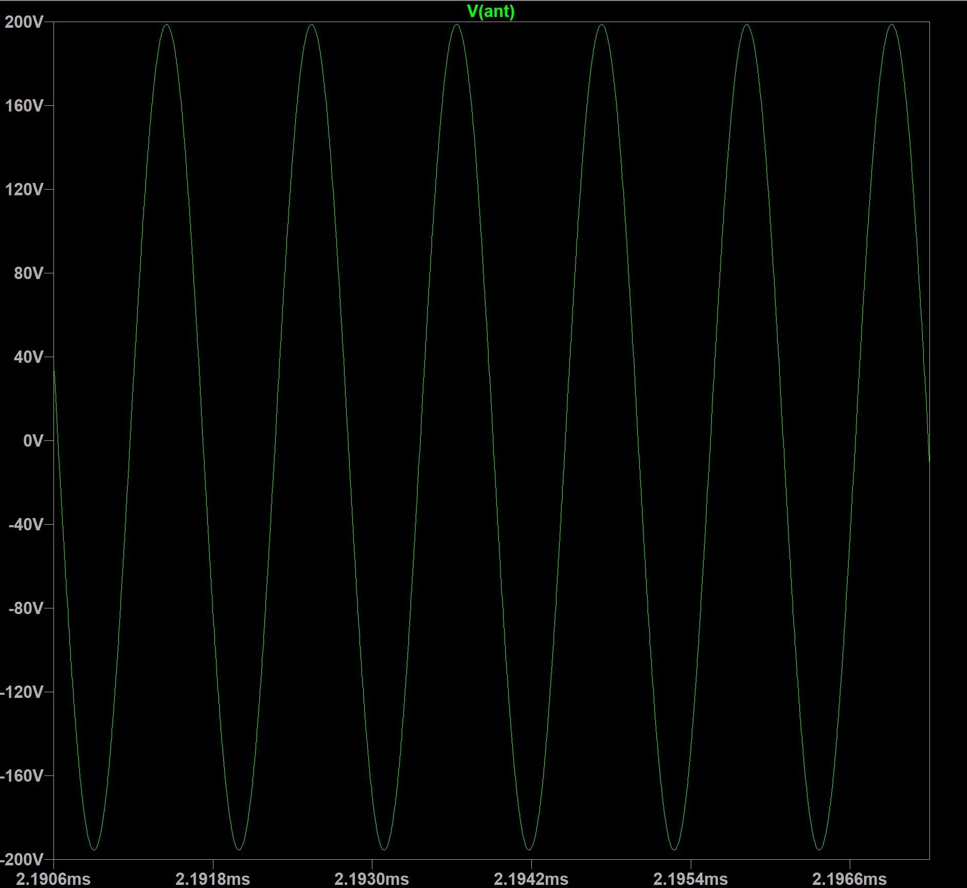
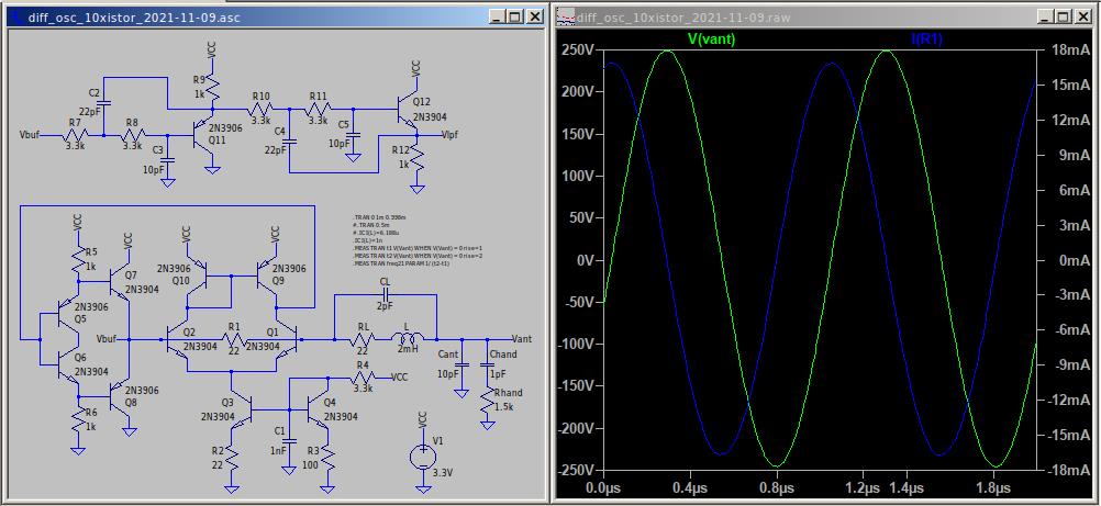
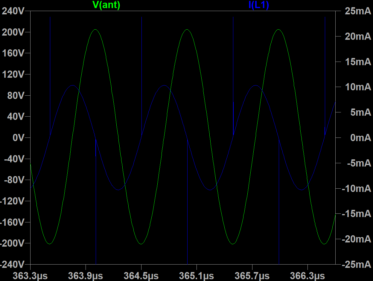
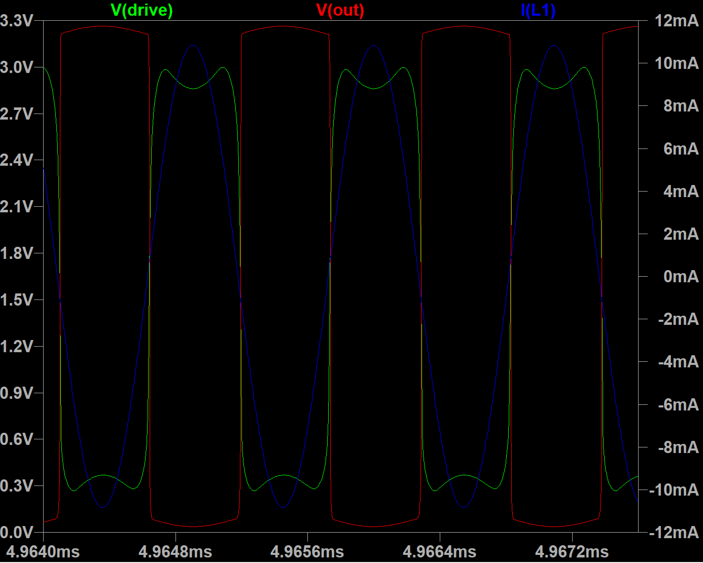
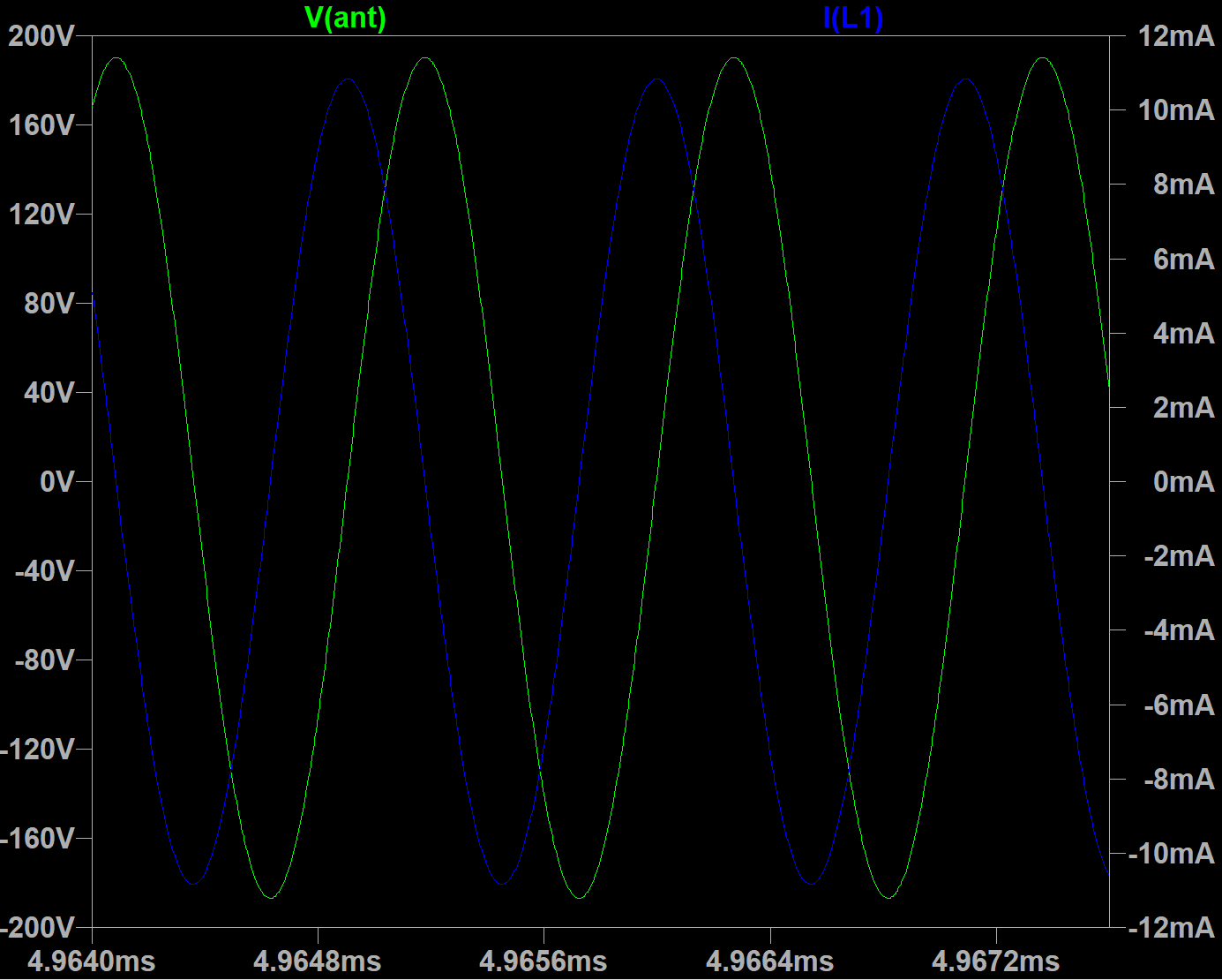
Antenna swing is 427 Vpp and inductor current is 12mA for dual drive inverters in parallel (for 2.7mH 120 Ohm inductor). Oscillator draws ~80mA in this configuration.
With 2.7mH 50 Ohm coil it may drive with 24mA current and produce 930Vpp antenna swing. Oscillator still draws 80mA in this mode.
LTSpice model link
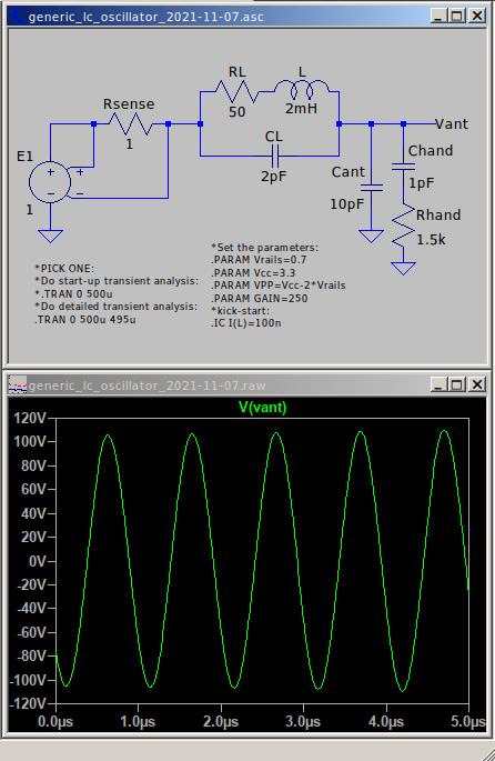
BTW, during searching for LVCU04 spice model, found crazy opamp made from unbuffered inverters