Armstrong, Hartley, Colpitts, Clapp, Wallin...

Posted: 11/6/2021 4:01:50 PM
Buggins

From: Porto, Portugal

Joined: 3/16/2017

Eric,

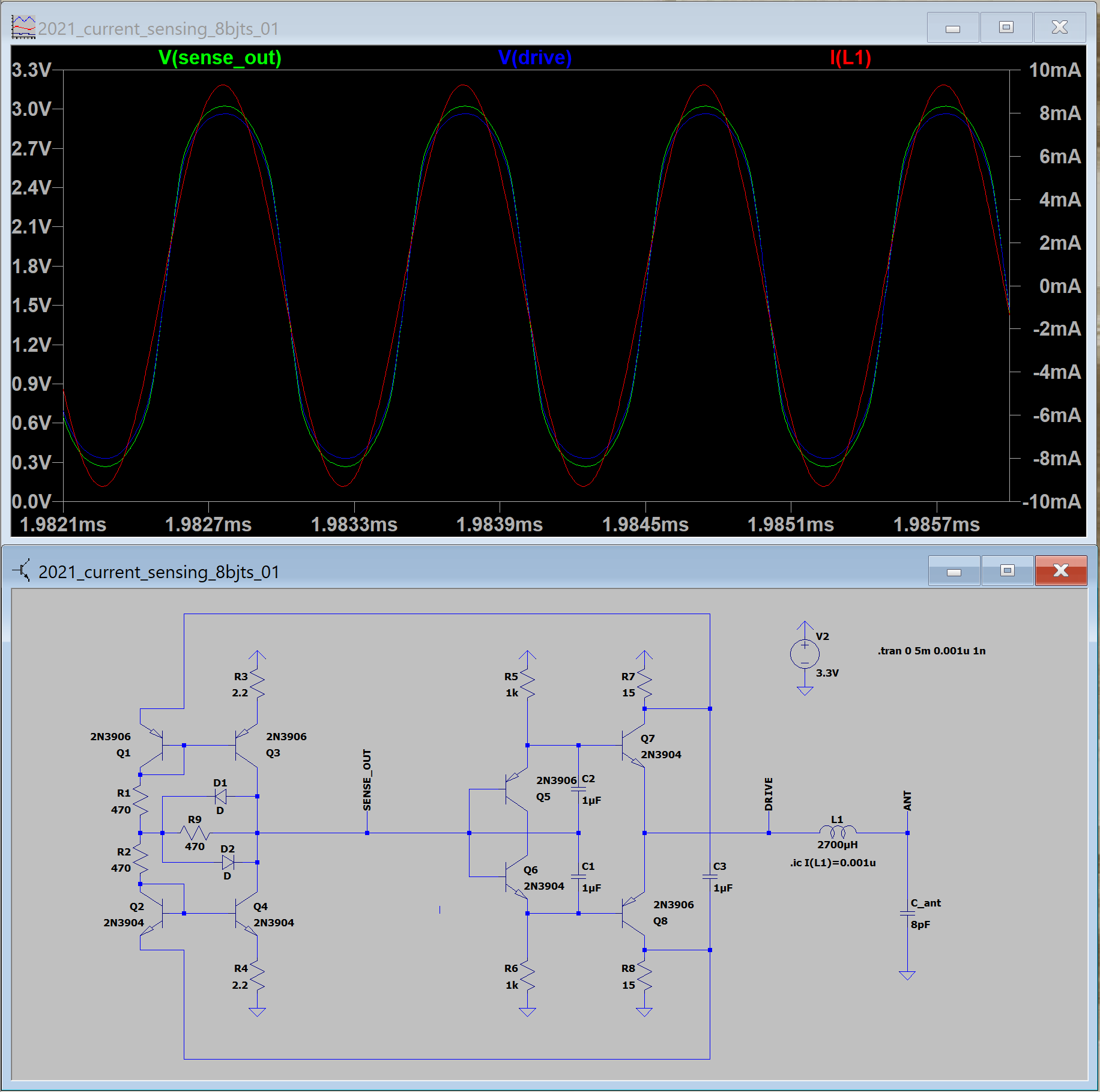
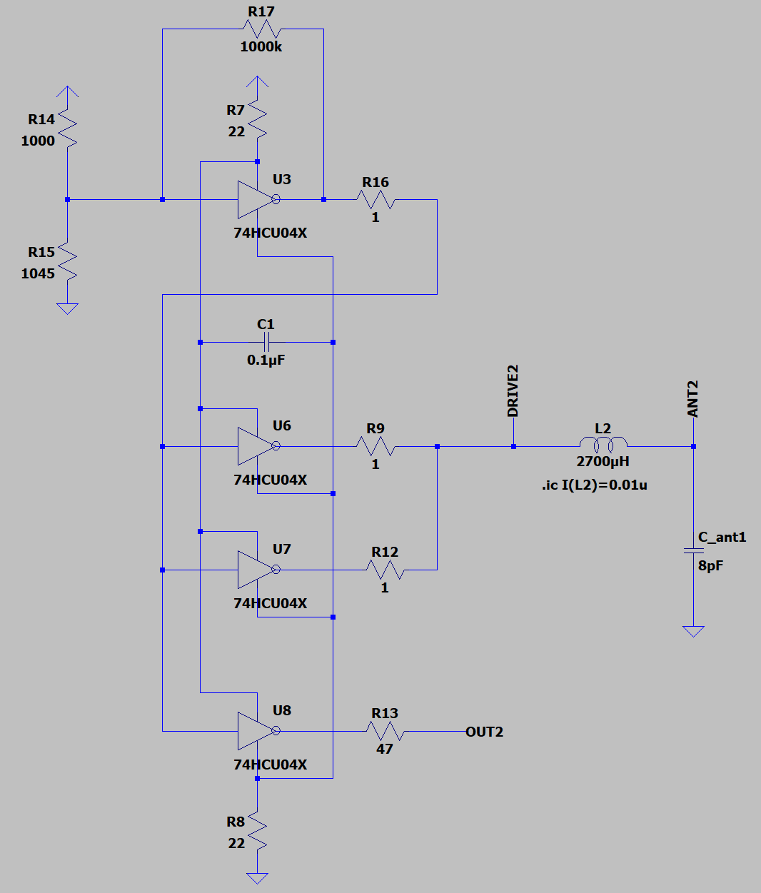
I've played a bit with your version of power rail current sensing model.
Tuned a bit.
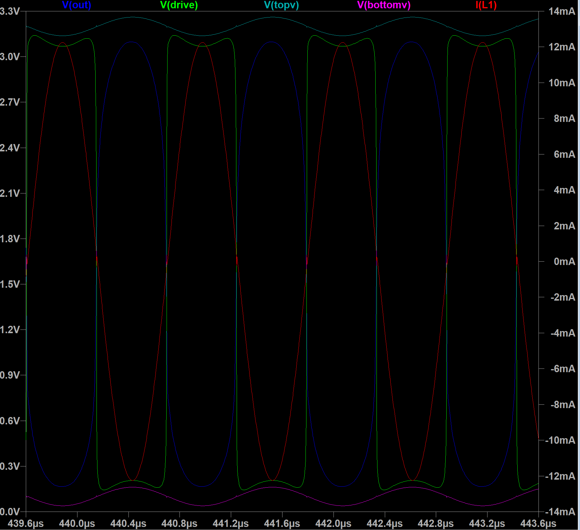
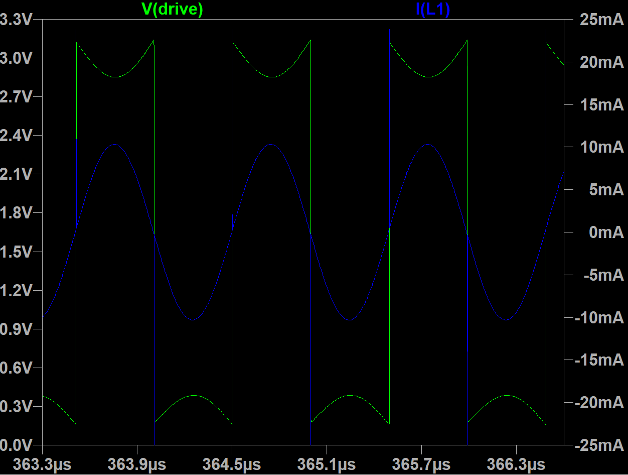
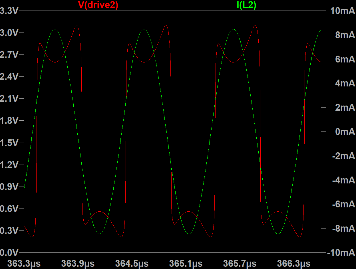
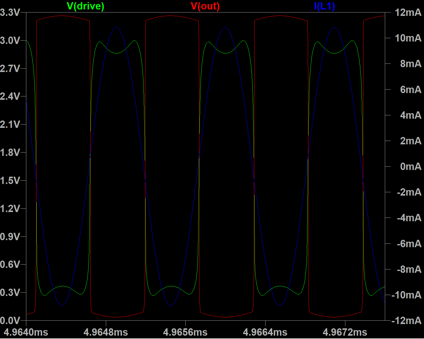
Drive signal is now symmetric and sine-like, ~2.6Vpp
Phase delay is only 12ns - better than most of my attempts of opamp oscillator design.
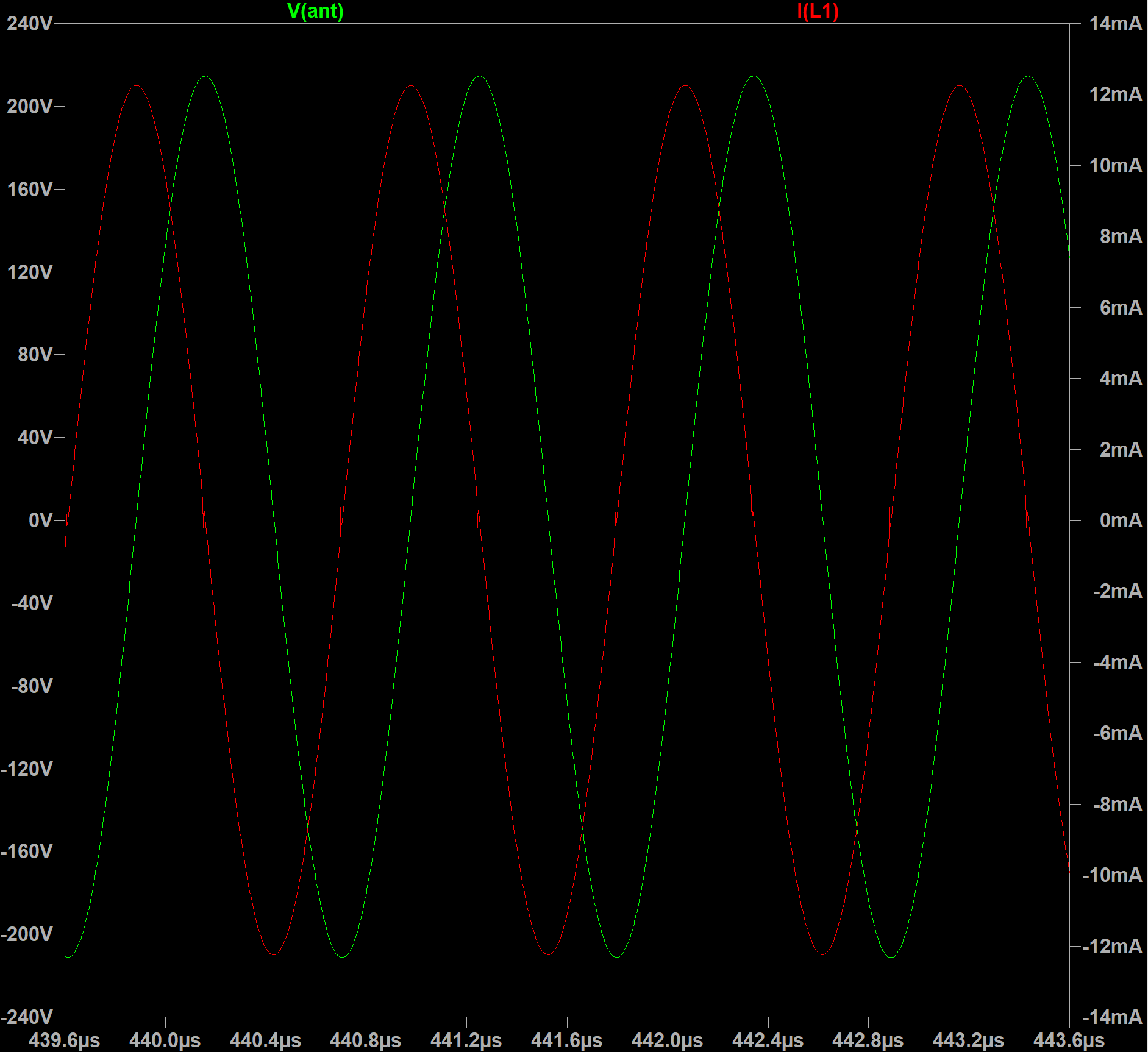
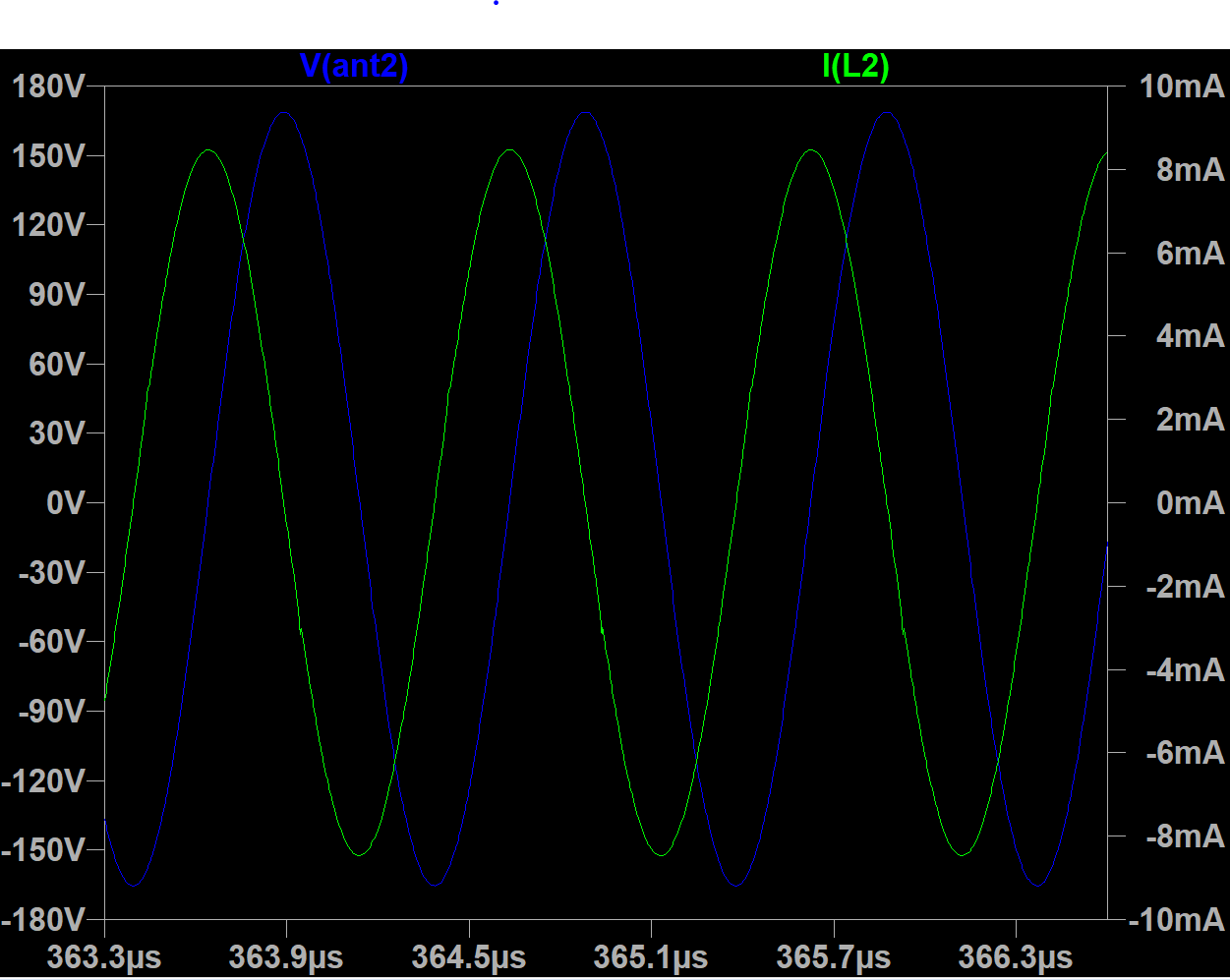
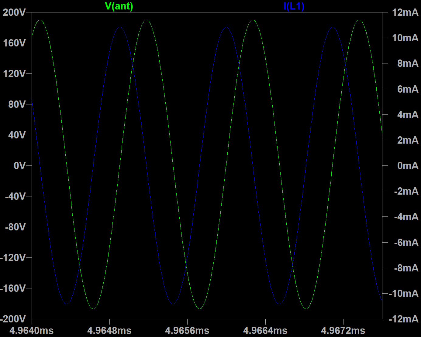
LC tank current is 9.4mA, antenna swing is 360Vpp - for 2.7mH 120 Ohm inductor. (23.5mA and 930Vpp for 50 Ohm inductor)

This schematic looks pretty usable for me.


LTSpice model download link

Posted: 11/7/2021 6:17:18 PM
dewster

From: Northern NJ, USA

Joined: 2/17/2012

"Drive signal is now symmetric and sine-like, ~2.6Vpp"  - Buggins

Vadim, you really know your way around LTSpice and analog!  I'm wondering though if sine-like drive is a good goal?  Hand damping is so strong that I think there should be sufficient reserve gain to make up for that, which generally means saturated / clipped drive with flat tops and bottoms.

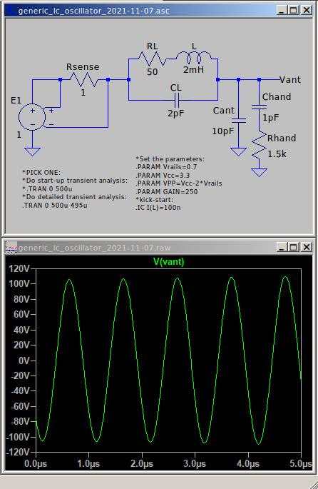
These transistor-based oscillators have become so complex that I've had to go back to basics to regroup my thoughts a bit with a more generic implementation [LINK]:

It's often difficult to get LTSpice do the full simulation without faulting out.  Anyway, it's interesting to see how much voltage gain across the 1 ohm sense resistor is needed to sustain oscillation.  Feedback consists of the current feeding the entire network of coil and antenna parasitics, and not just the idealized coil current, unfortunately.

Posted: 11/8/2021 8:45:08 PM
Buggins

From: Porto, Portugal

Joined: 3/16/2017


I'm wondering though if sine-like drive is a good goal?  Hand damping is so strong that I think there should be sufficient reserve gain to make up for that, which generally means saturated / clipped drive with flat tops and bottoms.

Obviously, square drive will give biggest possible voltage swing on antenna.
But I feel that we can get some benefits from limiting of drive signal spectrum (limited slew rate for square or clipping for sine). Lower noise?


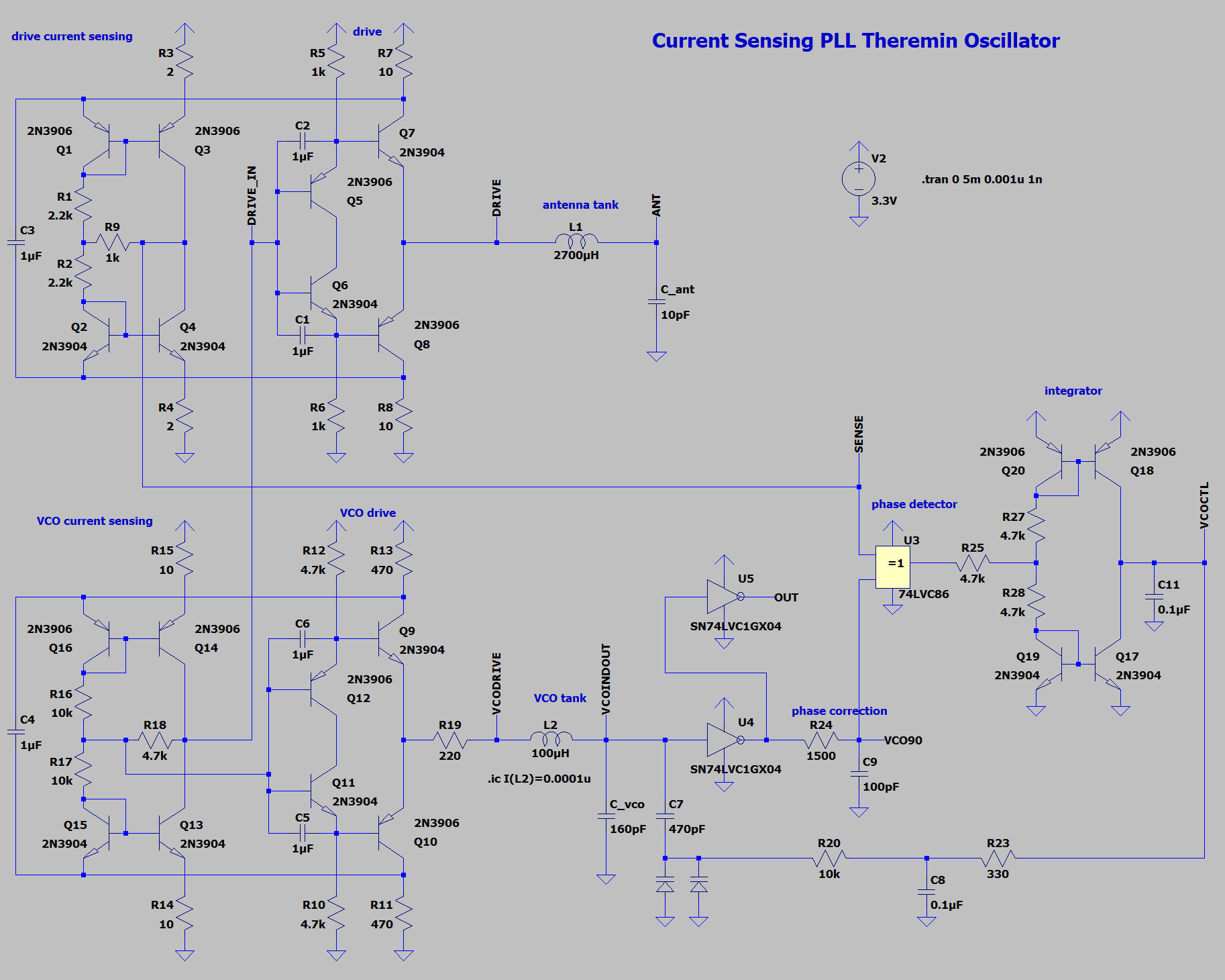
So far, I'm trying to design PLL based oscillator.
Back to BJTs. No opamps anymore.

20BJTs + two tiny logic ICs (one XOR + dual inverter).
Both VCO and antenna drive use similar output cascade and power rail current sensing current mirrors.
VCO provides two quadrature outputs - one for driving antenna tank, second for phase comparator.
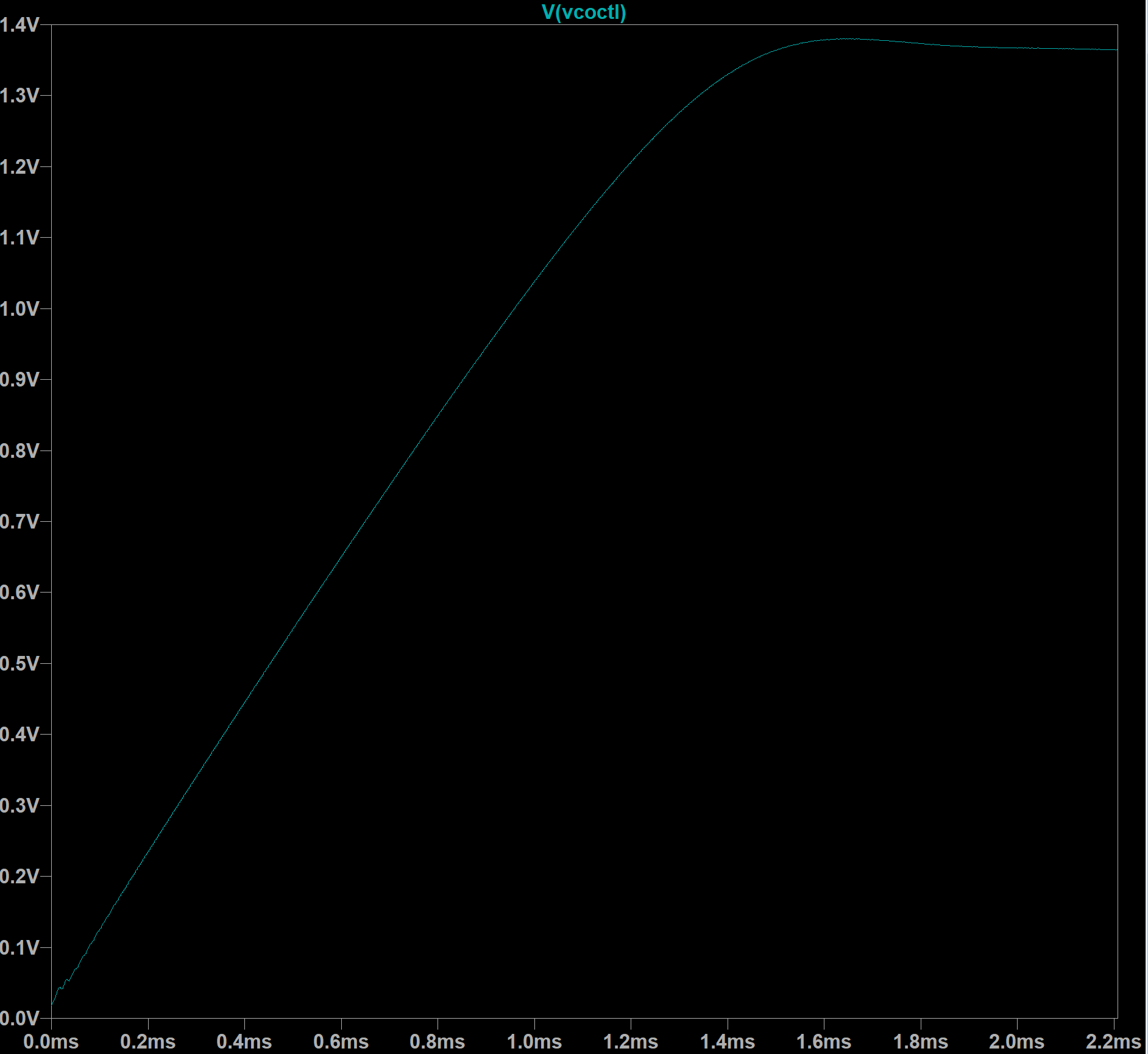
XOR based phase comparator followed by integrator is used to lock XOR inputs phase phase shift at PI/2.
Circuit may be tuned to achieve zero phase shift between antenna tank drive and current - using RC delay at one of XOR inputs.
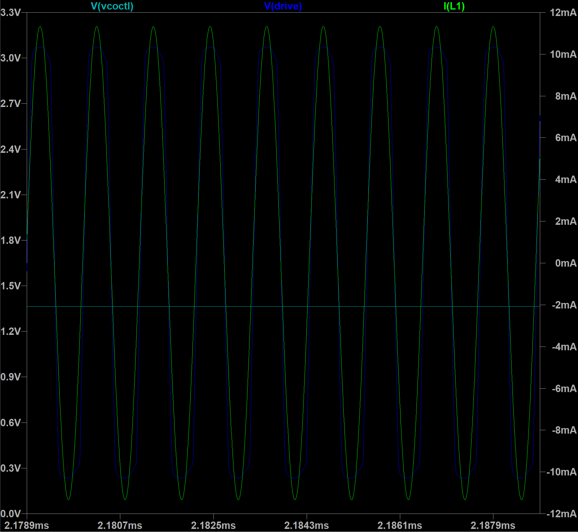
With PLL it's possible to reach pretty low phase error between drive and tank current (a few nanos) - impossible for usual current sensing drive.


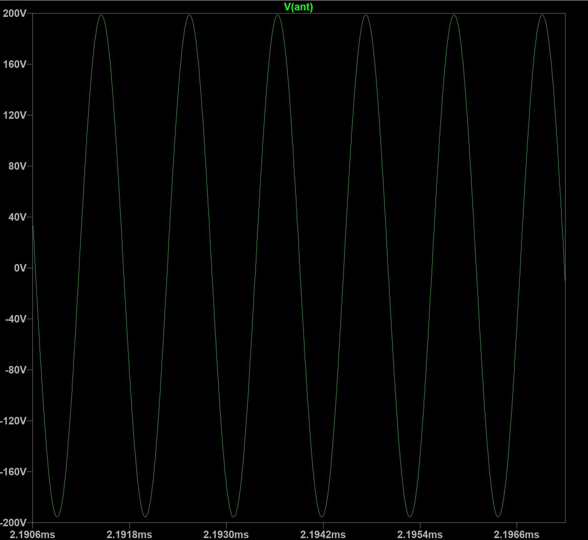
On 2.7mH 120 Ohm, it gives 2.84Vpp drive waveform, 11.3mA drive current, and ~400Vpp antenna voltage swing.


VCO Control Voltage - locking phase


LTSpice model download link

Posted: 11/9/2021 2:08:36 PM
dewster

From: Northern NJ, USA

Joined: 2/17/2012

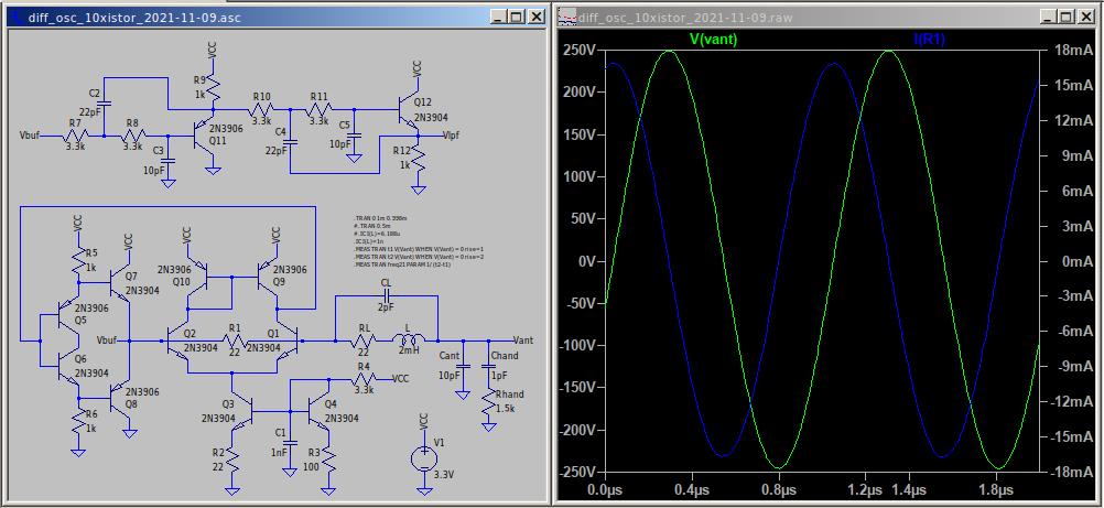
Differential Oscillator - 10 Transistor

Using a current mirror active load here for the differential pair which increases the gain.  Coil value and parasitics are somewhere around that of the D-Lev volume axis coil (fairly realistic).  We're basically constructing high speed op-amps here! [LINK]

Posted: 11/9/2021 3:19:49 PM
Buggins

From: Porto, Portugal

Joined: 3/16/2017


Using a current mirror active load here for the differential pair which increases the gain.  Coil value and parasitics are somewhere around that of the D-Lev volume axis coil (fairly realistic).  We're basically constructing high speed op-amps here!

Interesting improvement! 
I've tried it a few months ago but failed to get it working.

Posted: 11/9/2021 3:57:15 PM
Buggins

From: Porto, Portugal

Joined: 3/16/2017

Played a bit more with current sensing oscillator on inverters.

LTSpice or SN74LVC2GU04 model causes issues in simulation. Simulation results may be empty randomly, but working again after some change in model.

Several inverters may be connected in parallel to support bigger load.
In my model, more than two inverters in parallel usually do not work.
But even with a pair, there is 410Vpp swing on antenna and pretty small phase error : ~5ns
I hope, on a real hardware it will work better than on simulation.


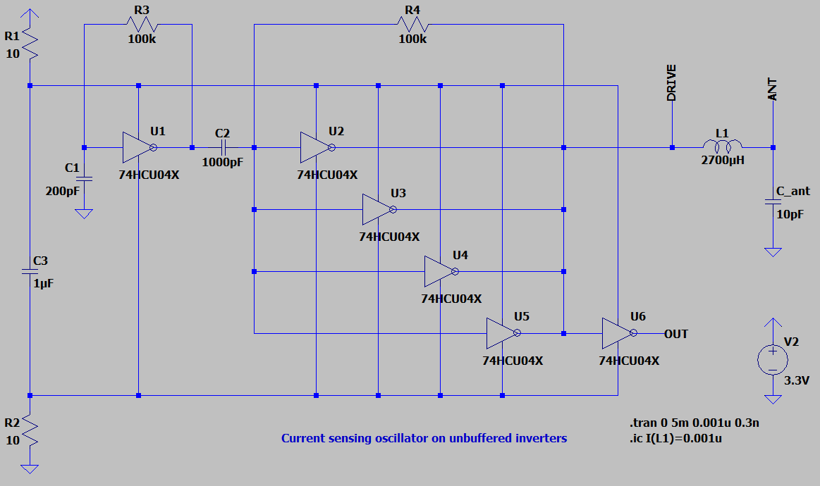
Just to check idea, tried it on 74HCU04 inverters.

Visible bigger phase error, but still good swing. With 74HCU04, 4 inverters may be used. Can be tested on breadboard.


LTSpice model download link (both models are in single file)

Posted: 11/9/2021 7:22:59 PM
dewster

From: Northern NJ, USA

Joined: 2/17/2012

"I've tried it a few months ago but failed to get it working."  - Buggins

Part of the trick I think is to not attach anything other than the buffer input bases to the high impedance collector.  Like not even bootstrapping capacitors.  I haven't quantified it at all, but I think the extra gain you get from the active load allows for a smaller sense resistor value?

Regarding your use of CMOS inverters, the Vcc/2 bias point set by divider R4/R5 is likely an issue for the real world circuit, as the inverter input threshold voltage is ill-specified.  I would use a feedback resistor (100k or more) from output to input of the inverter, and a series input capacitor (10pF or thereabouts) to self bias at least the input stage to its Vt.  Maybe also a capacitor from the intersection of R4/R5 to ground to decouple resistor noise, though that would also tend to couple in supply voltage variations.

Posted: 11/10/2021 11:37:50 AM
Buggins

From: Porto, Portugal

Joined: 3/16/2017


Part of the trick I think is to not attach anything other than the buffer input bases to the high impedance collector.  Like not even bootstrapping capacitors.  I haven't quantified it at all, but I think the extra gain you get from the active load allows for a smaller sense resistor value?

Yes, AFAIR, it worked fine until I connected load.


Regarding your use of CMOS inverters, the Vcc/2 bias point set by divider R4/R5 is likely an issue for the real world circuit, as the inverter input threshold voltage is ill-specified.  I would use a feedback resistor (100k or more) from output to input of the inverter, and a series input capacitor (10pF or thereabouts) to self bias at least the input stage to its Vt.  Maybe also a capacitor from the intersection of R4/R5 to ground to decouple resistor noise, though that would also tend to couple in supply voltage variations.

As usual, you've got a lot of nice advices! Thank you, Eric!
I have to learn more about using of unbuffered inverters in analog circuits.

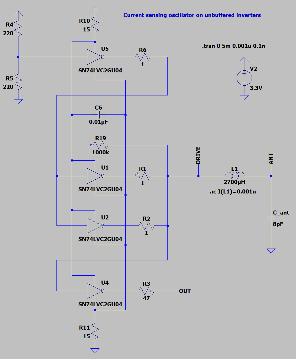
I've reworked 74HCU04 oscillator with feedback resistors and decoupling caps.
Magically, slow enough HC series inverters resulted to near zero phase error circuit.
C1, C2 allow tuning of phase shift - in both directions!

In simulation, it is working like a miracle. If worked in hardware, probably this is oscillator I wanted to design.
Probably, this single IC schematic is even cheaper than BJT based. Less soldering.

Tried 74LVCU04 inverters in simulation, and haven't managed to get it working.
Anyway, if cheaper HC series allows implementing of zero phase error oscillator, no reason to replace it with faster but more expensive one.

I believe, this oscillator can be easy converted into current sensing analog front end for FPGA PLL sensor.


LTSpice model download link

Posted: 11/10/2021 10:38:40 PM
dewster

From: Northern NJ, USA

Joined: 2/17/2012

Vadim, I've been playing with your interesting oscillator on a breadboard for a couple of hours, and it seems quite nice! 

I don't have 74HCU04 on hand, but I do have 74AHC04, 74HC04, 74LVU04.  LVU gives very rounded drive with obvious phase error and lower antenna voltage, and doesn't work well with my 0.5mH coil (stalls easily) though the drive duty cycle is 50/50.  HC has threshold problems I think, the drive duty cycle is roughly 60/40, though it gives sharp ringing drive and high voltages.  AHC seems to work best, with sharp ringing drive, no obvious major phase error, 50/50 drive, and high antenna voltages.  I see 220Vpp with the 0.5mH, 300Vpp with 3.7mH (with a small rod antenna).

I think it works better than my 8 transistor oscillator, particularly for smaller coils.  It gives higher voltage but more importantly it seems more stable, with less jiggling around at 16.666ms (1/60Hz) and less phase noise, though my bench is fairly noisy tonight.  It is fairly immune to supply voltage variation, which to me is always a good sign.  The 8 transistor is even more stable with supply voltage variation, and is harder to stall, but that's about it.

For my testing today I was using all 5 buffers in parallel to drive the coil.  I also used 22 ohm resistors to the rails rather than 10, which seemed to help a little with stalling @ finger pinch of the bare antenna rod.  A minor consideration is driving external things like processor or FGPA pins.  Using one of the buffers to do this (like you are doing above) is maybe good, but any line disturbance could possibly come back to the oscillator via current to/from the resistored drive rails.  I might use something like the two transistor 4th order LPF here driven from the supply rails to help isolate things, though I haven't actually tested that circuit on the bench yet.

One more thing that could be an issue is any hysteresis they sometimes build into these parts to help reject digital noise.  I think the AHC parts have it, and I keep waiting to get bitten by it on the D-Lev.

Posted: 11/11/2021 5:10:01 PM
Buggins

From: Porto, Portugal

Joined: 3/16/2017


Vadim, I've been playing with your interesting oscillator on a breadboard for a couple of hours, and it seems quite nice!


Wow! It's pretty good news. Thank you for trying it in hardware. Unfortunately my one year old son prevents me from soldering and breadboarding experiments.


I don't have 74HCU04 on hand, but I do have 74AHC04, 74HC04, 74LVU04. 
LVU gives very rounded drive with obvious phase error and lower antenna voltage, and doesn't work well with my 0.5mH coil (stalls easily) though the drive duty cycle is 50/50.  HC has threshold problems I think, the drive duty cycle is roughly 60/40, though it gives sharp ringing drive and high voltages.  AHC seems to work best, with sharp ringing drive, no obvious major phase error, 50/50 drive, and high antenna voltages. 
I see 220Vpp with the 0.5mH, 300Vpp with 3.7mH (with a small rod antenna).

Have you really tried buffered inverters? I didn't expect that they would work

For LVU, you can try changing sensing inverter input cap value - it allows changing of phase. Probably, it's possible to achieve zero phase error by using of proper decoupling capacitor and feedback resistor. I believe, input cap should be tuned for different LC tank frequency.

Does inverter bases current sensor oscillator survive hand touching antenna?

I think it works better than my 8 transistor oscillator, particularly for smaller coils.  It gives higher voltage but more importantly it seems more stable, with less jiggling around at 16.666ms (1/60Hz) and less phase noise, though my bench is fairly noisy tonight. 
It is fairly immune to supply voltage variation, which to me is always a good sign. 
The 8 transistor is even more stable with supply voltage variation, and is harder to stall, but that's about it.


For my testing today I was using all 5 buffers in parallel to drive the coil.  I also used 22 ohm resistors to the rails rather than 10, which seemed to help a little with stalling @ finger pinch of the bare antenna rod.  A minor consideration is driving external things like processor or FGPA pins. 
Using one of the buffers to do this (like you are doing above) is maybe good, but any line disturbance could possibly come back to the oscillator via current to/from the resistored drive rails. 
I might use something like the two transistor 4th order LPF here driven from the supply rails to help isolate things, though I haven't actually tested that circuit on the bench yet.


Good point regarding output line noise. Output implementation should be changed.

One more thing that could be an issue is any hysteresis they sometimes build into these parts to help reject digital noise.  I think the AHC parts have it, and I keep waiting to get bitten by it on the D-Lev.

I believe only buffered inverters have hysteresis. But oscillators are analog devices, and I believe it's better to use unbuffered inverters there.


Update on my simulation experiments.


Found LVCU04 spice model from NXP. It's working w/o bugs unlike TI one.
74hcu04 inverter draws 2.5mA in "analog mode" (when input is close to VCC/2).
74lvcu04 inverter draws ~20 times more - 45mA.
When sensing 74lvcu04 is powered in parallel with drive inverter, it causes constant 45mA current through sensing resistors and hence reduces drive voltage swing.
Let's extract sensing inverter - power it directly from power rails, and feed with middle of drive power pins.
Sensing signal becomes inverted, and now requires additional inverter.
Second inverter output looks nice for output source - smooth waveform should cause less ringing in line. Noise from output line now do not go through sensing resistors, and at least is not being amplified by current sensor.
Eric, do you think it's ok to implement output this way? If so, only two 74LVC2GU04 ICs are needed.


Phase error still may be corrected by changing of sensing inverter input decoupling capacitor.
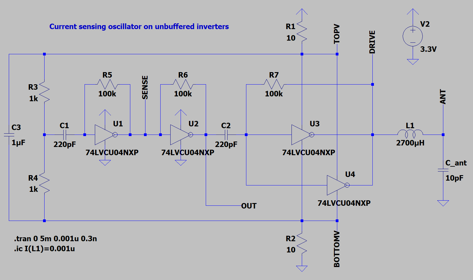


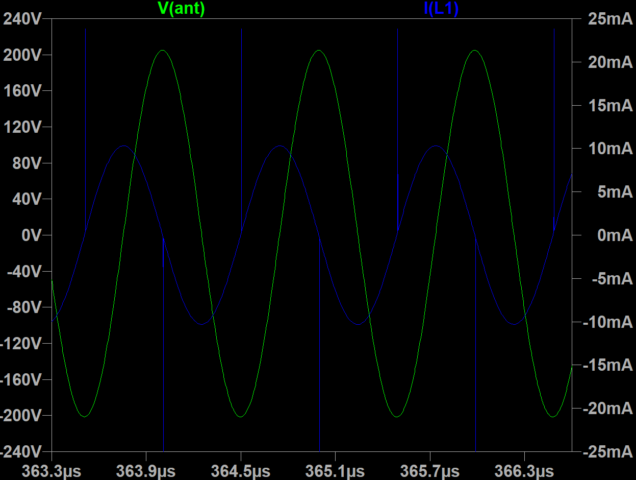
Antenna swing is 427 Vpp and inductor current is 12mA for dual drive inverters in parallel (for 2.7mH 120 Ohm inductor). Oscillator draws ~80mA in this configuration.
With 2.7mH 50 Ohm coil it may drive with 24mA current and produce 930Vpp antenna swing. Oscillator still draws 80mA in this mode.

LTSpice model link

BTW, during searching for LVCU04 spice model, found crazy opamp made from unbuffered inverters

You must be logged in to post a reply. Please log in or register for a new account.