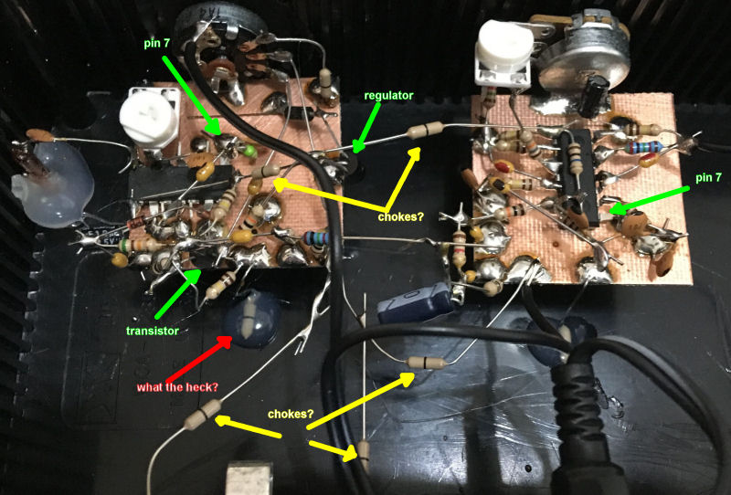
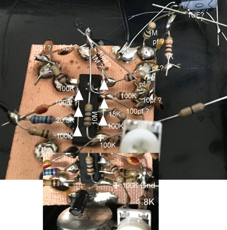
I'd previously encountered one or more pictures of the internals of the Burns B3 elsewhere on the web, but couldn't locate them again lately via various web searches. Recently TW member Spiratonic graciously posted two pics of the internals, which I then stuck in a TW photo album [LINK] so we all get to see what's in there:

The "dead bug" layout looks super labor intensive to me for such a simple circuit. I would think a PCB would be the order of the day for a product listed on Amazon. IMO, anything based on CMOS should socket the ICs - good luck repairing this!
The more I look at it the more I'm pretty sure its CMOS inverter based because of what looks like 14 pin DIPs with many adjacent pins connected together (thus chaining inverter I/O), and you can see one corner pin (7) on each is clearly ground supply, with the opposite corner pin (14) clearly positive supply. There are two TO-92 packages, one is obviously a voltage regulator because it's fed by a rectifier coming from a separately elevated portion of the PWB which is connected to the pot power switch. The things that look like resistors with a single band down the middle could be chokes of some sort, but I only see them in what appear to be power feed and audio RF filtering situations, so probably no LC resonance going on.
There's a mysterious component with one end grounded, the other end apparently missing, with the whole thing embedded in a gob of silicone? [EDIT] There's on on the other board too! Looks like a jury-rigged board support.
Anyway, without a longer & better look at it, I'd say it's an RC CMOS Theremin.
Thanks again to Spiratonic for the pix!


