

 By: Max Baars
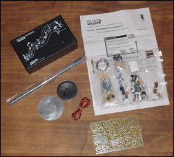
The theremin kit as sold by Jaycarhas good value for money. You receive a complete theremin with both pitch and volume control.
However I found some aspects of this theremin less appealing and tried to modify the original circuit to deal with them. I've drawn all mods into the original circuit diagram for you to compare.
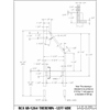
circuit diagram (gif 74k)
modified circuit diagram revision 4 (jan 23, 2004) (gif 84k)
circuit board (gif 101k)
placement (gif 78k)
I will run trough the mods explaining what and how:
Power supply - Bad design. A 78xx regulator should not be loaded with such large capacitors as oscillation may occur. I've put one 470 uF cap at the regulator's input and only a 100 nF at the output. Some of the original caps are not located near the 7805, it's a bit of a search to find the right ones..
Learn more
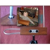
Volume antenna- A bit small... I've replaced it with a traditional loop as seen on most theremins (like the etherwave). This has a positive effect on volume control as well. And it looks much better..
Volume control amplifier - This one is difficult to adjust. Therefore I made some mods here as well. Before playing the theremin you need to do some fine-tuning to compensate for drift in the volume oscillator and to adjust the response to your needs. It seems a common solution to use a panelmount pot instead of the trimpot VR2. This is not wise though. First, this pot is tricky to adjust and second, it has a entirely different function!
The way the volume control works is as follows: T3 is set to a certain frequency. That frequency will get lower if you approach the antenna. T4 is adjusted to a frequency slightly higher than T3. Therefore the output of T4, which is a band filter, will decrease when the frequency of the oscillator gets lower.
This voltage is then amplified and level-shifted by the LM358. VR2 is part of this amplifier and takes care of the level-shifting.
Now, fine-tuning the volume oscillator has to do with making shure that the frequency of T4 is slightly higher than the frequency of the volume oscillator. Thus obviously fine-tuning has to be done either around T4 or in the volume oscillator. That last option is the easiest.
The oscillator can be fine-tuned by slightly varying the drain current of the FET. This can simply been done by replacing the fixed 100 ohm resistor at Q3 with a series connection of a 100 ohm resistor and a 500 ohm pot. This pot can be panelmount to allow adjustment from the outside.
In addition I've changed the 1 Meg resistor between pins 2 and 3 of the LM358 into 220 k. With the original 1 Meg resistor there is way to much gain with as result that little handmovement has already a big effect on the volume. With the new resistor I have about 15" playroom to go from silence to max. volume.
Adjustment procedure (keep distance from volume antenna):
1 - Set the core (slug) of T3 and T4 in their top position, set the new volume fine-tuning pot in the mid position.
2 - Measure the voltage on pin 3 of the LM358 and adjust T4 for max. voltage.
3 - Measure the voltage on pin 1 of the LM358. Adjust VR2 so that the voltage reads about 4.0 volt*.
4 - Turn T4 a bit back, so that the voltage just starts to drop to about 3.5 volt.
5 - Check the volume responce by moving your hand. If the control area is to small tweak T4 slightly.
*) If you adjust in such way that 4.3 volt is measured when you move away from the antenna, the volume response is not very smooth, therefore I recomment to adjust the instrument in such way that you end up with 3.5 volt at step 4.
Fine-tune possibility for pitch- It's hard to exactly tune the instrument with adjusting T1 and T2, and beyond that, one needs to be able to tune the instrument without opening the box. fine-tuning can be done by varying the length of the telescoping antenna. However I replaced that antenna with another rod and thus have lost that option. The pitch oscillators can be fine-tuned by slightly varying the drain current of the FET. This can simply been done by replacing the fixed 1 k resistor at Q1 with a series connection of a 470 ohm resistor and a 1 k pot. This pot can be panelmount to allow adjustment from the outside. It may be wise to use screened wire to connect the pot and somehow fix the wires to the cabinet because vibrations in the wires may modulate the oscillator and thus the audio signal.
Linearizing the pitch sensitivity- I found that the upper octave was much compressed and that the highest notes I wanted to play were so close to the antenna that accurate vibrato wasn't possible. A way to linearize the response is to put an inductor in series with the antenna. I've drawn a graph of the original situation and the corrected pitch linearity. The vertical axis shows distance to the antenna in cm, the horizontal axis shows the octaves.
Which basicly means that if you add a pitch linearizing coil and are are not satisfied with the response, you may try to both adjust T1 and T2 one or two turns clockwise or counter clockwise and see what that does to the response. The entire circuit is a complex mechanism, where the antenna's capitance interacts with the coil in T2, while the new coil interacts with the capacitor in T2. This is normal in RF technology and you can either attack this with a lot of math or with trial and error. It also means that you may want to try to keep some clearance around the coil and cabinet to avoid spoiling it's Q factor.
Here are some examples of antenna dimensions and their resulting coil values. I'm using an air-would coil, mounted vertically. Be aware that the examples only apply to the SC theremin kit since the pitch oscillator frequency is one of the variables in the calculation.
Sound - The original sound of this theremin is a rather clean sinewave with some buzz-like distortion at max. volume (caused in the LM358). I don't want a clean sinewave but more a string-like sound.
I replaced above mod. with the following:
I removed the 10 k trimpot and 220 pf capacitor. Then I took some 1 mm massive wire, two pieces of 10 cm. I bend these into an L shape, with the short end being 1.5 cm and the long side 8,5 cm. And soldered one at the 100 k resistor rear Q1, at the side that connects to the 68 pf cap. The other wire is soldered to the 100 k resistor near Q2, again at the side that connects to the 68 pf cap.
The are soldered in such way that the 1.5 cm part is vertical and the 8.5 cm part is horizontal. The horizontal parts are in parallel and have a space of about 0.5 to 1 cm. These now can be bend closer to each other or further away to modify the sound. If they are to close you will loose the lower notes. This is a trade off just as the old mod. was.
This new mod. works similar to the previous mod. but has a different sound as result which I like better.
To modify the sound further, I replaced the 1 k resistor between pins 2 and 3 of the MC1496 with 2k2. This reduces the conversion gain somewhat, which has a positive effect of the max. volume distortion and at the same time makes low volume signals slightly more 'raw' like slowly bowing a violin.
Due to the added low-pass filter the wave becomes more like a sine at higher frequencies.
There are many variations possible by adjusting the two new trimpots, it's all a matter of taste.
Next I created a low-pass filter between the MC1496 and the LM358 by putting a 100 k trimpot in series with the 0.1 uF capacitor and add a 10 nF capacitor between pins 4 and 5 of the LM358. This allows to take the sharp edge of the signal and makes it more like the sound of strings. It also slightly reduces the signal level which further cures the distortion at max. volume.
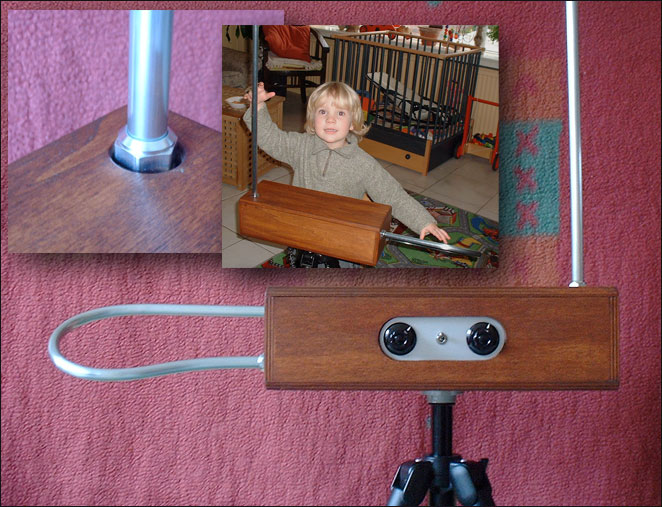
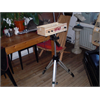
The two knobs on the front are volume and pitch fine-tuning.
There is a t-nut, centered in the cabinet bottom for mounting the theremin on a sturdy Manfrotto 144B tripod.
Results - are hard to describe in words. [Sound samples pending- TW Staff]
Before you start soldering, please be aware that you can do damage if you make mistakes. Please only modify your circuit if you know what you are doing. After all it would be a shame if you would break it (and I don't want to get the blame if you do).
Enjoy! Max


